
A self-locking clutch device

A clutch device and self-locking technology, applied in the field of self-locking clutch devices, can solve problems such as large power consumption, and achieve the effects of saving power, simple structure and large transmission torque

Active Publication Date: 2017-09-12
SHANGHAI AEROSPACE SYST ENG INST
View PDF6 Cites 0 Cited by
  • Summary
  • Abstract
  • Description
  • Claims
  • Application Information

AI Technical Summary

Problems solved by technology

[0003] In order to solve the problem of consuming a large amount of electric energy to maintain the clutch state in the prior art, the present invention provides a self-locking clutch device

Method used


Image

  • A self-locking clutch device
  • A self-locking clutch device
  • A self-locking clutch device

Examples


Embodiment Construction

[0019] Preferred embodiments of the present invention will be described below in conjunction with the accompanying drawings.

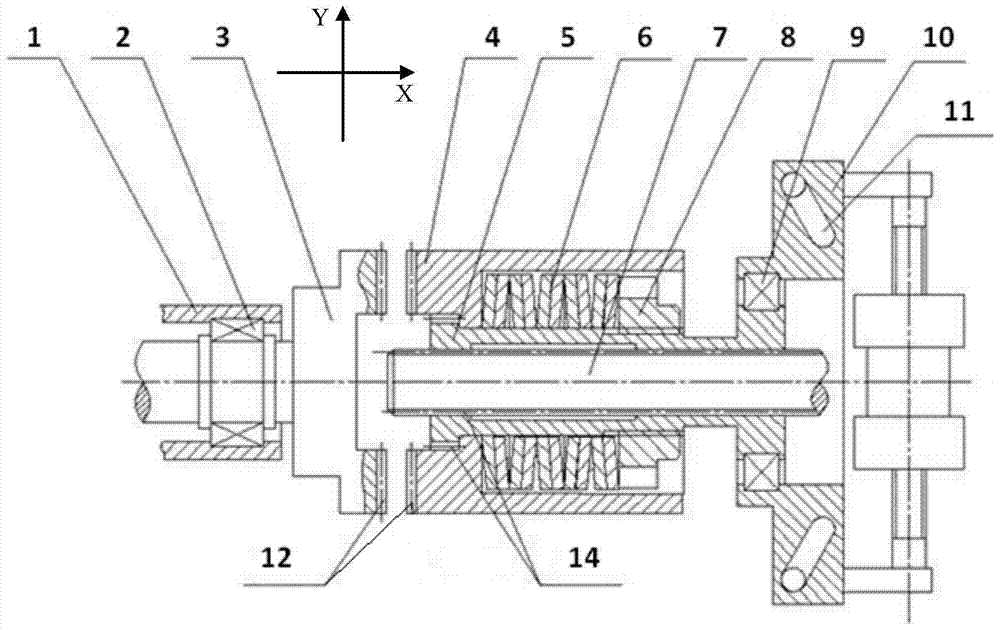
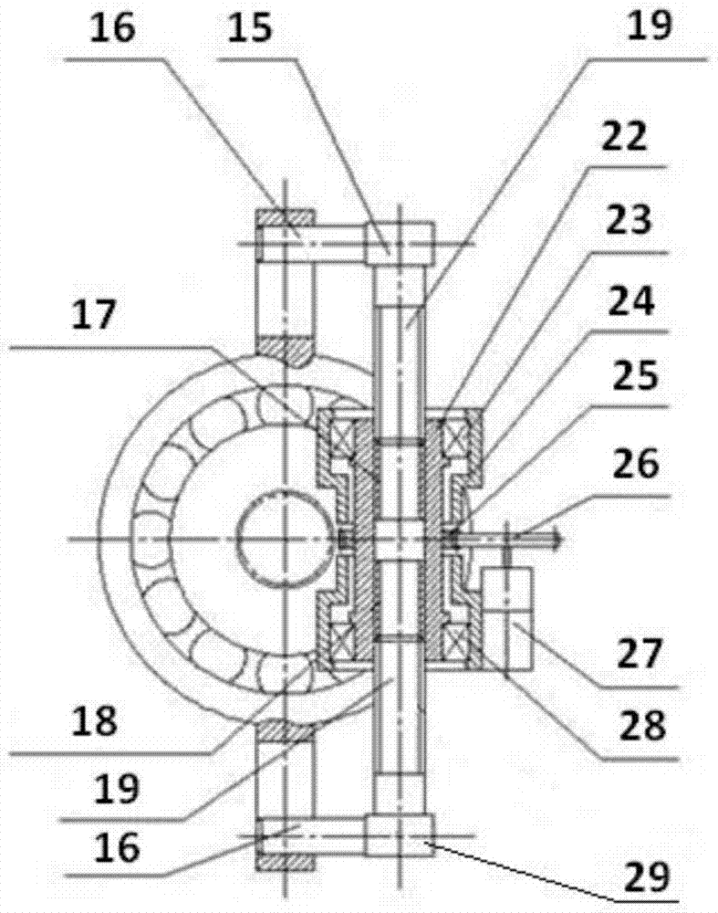
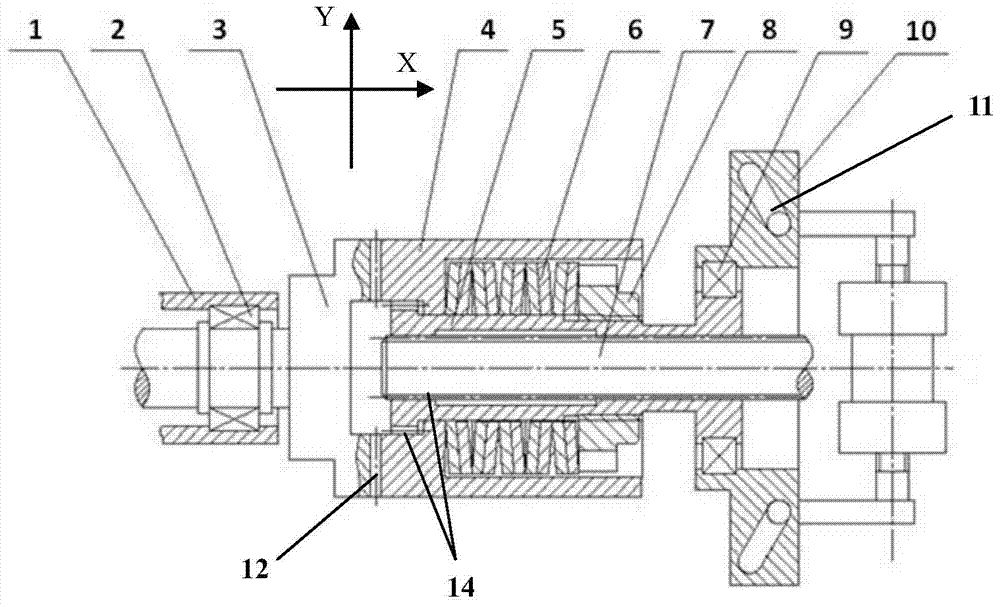
[0020] Such as figure 1 To such as Figure 4 As shown, the X axis is the axial direction of the input shaft and the output shaft, and the Y axis is the radial direction.

[0021] The output shaft 3 is supported on the output shaft housing 1 through the output shaft bearing 2 and can rotate relative to the output shaft housing 1 . The output shaft 3 has an end surface tooth structure 12 . The sliding shaft 5 is connected with the sleeve 4 through a spline 14 and can slide relative to the sleeve 4 along the X-axis. There is a tooth structure 12 on the end surface of the sleeve 4, which can engage with the tooth structure 12 on the end surface of the output shaft 3. The wing nut 8 is fixed on the outside of the sliding shaft 5, and the disc spring 6 is connected to the sleeve 4 and the wing nut 8 at both ends along the X-axis. The sliding shaft 5 is ...


PUM


Abstract

A self-lock type engaging and disengaging device comprises a belt speed reducer motor, pin drive structures, pin structures, a sliding disc, an input shaft, a sliding mechanism and an output shaft structure. The belt speed reducer motor drives the two pin structures to move along the Y axis through the pin drive structures. The pin structures move along the Y axis to drive the sliding disc to slide along the X axis and then drive the sliding mechanism to slide along the X axis, and finally engaging and disengaging between the sliding mechanism and the output shaft structure are achieved through sliding of the sliding mechanism along the X axis. The self-lock type connecting and disconnecting device has the advantages of being rapid in engaging and disengaging, large in transmitting torque and capable of achieving the self-lock keeping state after outage and meanwhile, has the beneficial effects of being simple in structure and low in weight.

Description

technical field [0001] The invention belongs to the technical field of mechanical transmission clutch, in particular to a self-locking clutch device for transmission engagement and disconnection of a spacecraft. Background technique [0002] At present, in the known space vehicle mechanical transmission devices, the switching of power transmission is mostly realized by electromagnetic clutches. There are two working modes of the clutch: one is energized to engage, and the other is energized to disconnect. Both methods require energization to operate the engaged or disengaged state. If the aircraft needs to maintain this state for a long time, it needs to be powered on all the time, which consumes a lot of electric energy, which is a big waste for spacecraft with relatively tight energy supply. Contents of the invention [0003] In order to solve the problem in the prior art that a large amount of electric energy is required to maintain the clutch state, the present invent...

Claims


Application Information

Patent Timeline
Patent Type & Authority Patents(China)
IPC IPC(8): F16D28/00
CPCF16D28/00F16D2500/1025
Inventor 沈晓鹏路火平魏智丁立超傅丽佳
Owner SHANGHAI AEROSPACE SYST ENG INST
Learn More