Slewing bearing

A technology of slewing bearings and rotating rings, which is applied in the field of bearings, can solve the problems of limited application occasions of slewing bearings, the inability to apply slewing bearings and narrow installation space, etc., and achieve the effect of simple installation process

Active Publication Date: 2016-04-06
SCHAEFFLER TECH AG & CO KG
View PDF5 Cites 5 Cited by
  • Summary
  • Abstract
  • Description
  • Claims
  • Application Information

AI Technical Summary

Problems solved by technology

[0007] The problems solved by the present invention are: 1. The external braking mechanism will limit the application occasions of the slewing bearing, for example, the slewing bearing with the external braking mechanism cannot be applied to occasions where the installation space is narrow;

Method used


Image

  • Slewing bearing
  • Slewing bearing
  • Slewing bearing

Examples


Embodiment Construction

[0028] In order to make the above objects, features and advantages of the present invention more comprehensible, specific embodiments of the present invention will be described in detail below in conjunction with the accompanying drawings.

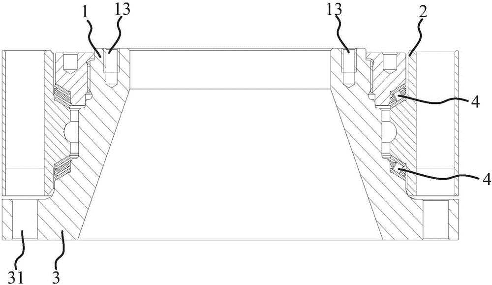
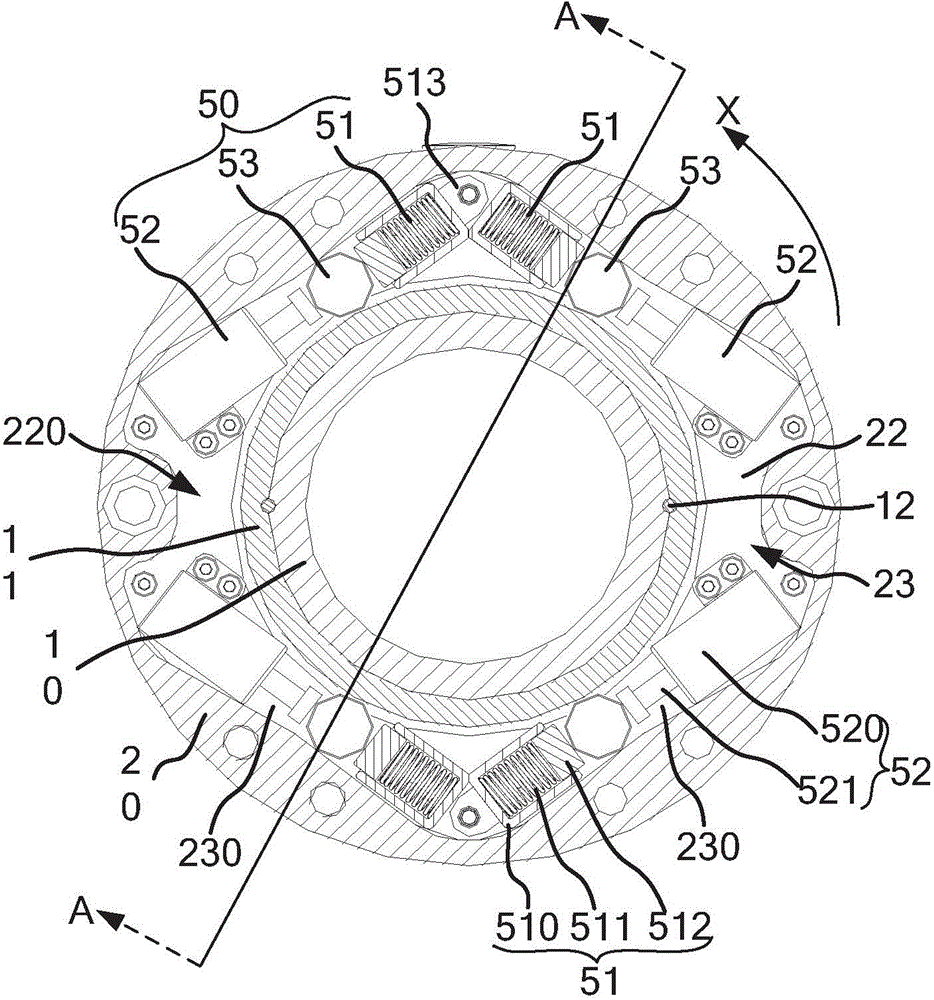
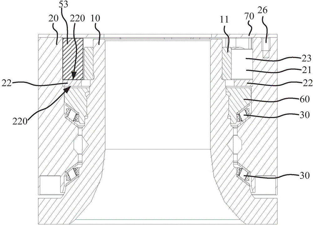
[0029] refer to figure 2 , image 3 , the slewing bearing includes: a rotating inner ring 10, a non-rotating outer ring 20, a number of rolling elements 30 located between the inner ring 10 and the outer ring 20, the rolling elements 30 constitute two sets of angular contact thrust bearings, the inner ring 10 Coaxial with the outer ring 20, the inner ring 10 can rotate relative to the outer ring 20, a number of threaded holes 26 are provided on the axial end surface of the outer ring 20, and a mounting surface of the rotary structure is connected to the outer ring 20 through the several threaded holes 26 . There is a radial gap 21 between one end of the outer ring 20 having a threaded hole 26 and the inner ring 10 , and a support member...


PUM


Abstract

A slewing bearing comprises an inner ring, an outer ring and multiple rolling bodies located between the inner ring and the outer ring; one of the inner ring and the outer ring is a rotary ring, and the other is a non-rotary ring; a supporting part is installed on the non-rotary ring and at one end in the axial direction of the slewing bearing and is back on to the surfaces of the multiple rolling bodies, the inner ring and the outer ring in the axial direction to define a containing chamber; at least two brake mechanisms are arranged in the containing chamber; at least one of the brake mechanisms is used for locking and unlocking when the rotary ring rotates clockwise, and at least the other brake mechanism is used for locking and unlocking when the rotary ring rotates anticlockwise. The brake mechanisms are integrated in the slewing bearing through the supporting part. The brake mechanisms do not limit the application occasions of the slewing bearing, and the installation process is simple and convenient.

Description

technical field [0001] The invention relates to a bearing, in particular to a slewing bearing. Background technique [0002] The slewing bearings of the prior art cannot be mounted to an external slewing structure in the axial direction if the installation space on one of the mounting sides is limited. In order to solve the above problems, the applicant once proposed a solution to solve the above problems, which is: [0003] refer to figure 1 , the slewing bearing includes a coaxial inner ring 1, an outer ring 2 surrounding the inner ring 1, an outer ring 3 surrounding the inner ring 1 and connected to the inner ring 1, the outer ring 3 is axially opposite to the outer ring 2, and the inner ring 1 There are two sets of rolling elements 4 separated from each other between the outer ring 2 and the outer ring 2 . [0004] On the end surface of the outer ring 3 opposite to the outer ring 2 , a plurality of first threaded holes 31 are arranged at intervals along the circumfere...

Claims


Application Information

Patent Timeline
Patent Type & Authority Applications(China)
IPC IPC(8): F16D41/06
Inventor 潘仁会沈彦斌张建昌
Owner SCHAEFFLER TECH AG & CO KG
Why Eureka
Try Eureka