LED (Light Emitting Diode) lamp

A technology of LED lamps and lamp holders, which is applied in the direction of lighting devices, cooling/heating devices of lighting devices, light sources, etc., and can solve the problem of uneven distribution of light emitted by light emitting units on the surface of the lamp housing, uneven distribution of brightness on the surface of the lamp housing, and heat dissipation effects. Poor and other problems, to achieve uniform brightness, improve the brightness of the irradiation, increase the effect of heat dissipation space

Inactive Publication Date: 2016-04-06
莆田康布斯光电科技有限公司
View PDF8 Cites 0 Cited by
  • Summary
  • Abstract
  • Description
  • Claims
  • Application Information

AI Technical Summary

Problems solved by technology

[0002] In the prior art, the light-emitting unit is mostly fixed in the middle of the lamp housing. The light-emitting unit of the LED lamp includes a substrate and an LED die attached to the substrate. The LED die is distributed on one side of the substrate, and the other side of the substrate is connected to the The component is connected to the lamp holder. The side with the bare LED attached to the substrate is facing the front of the lamp housing, and the other side of the substrate is facing the lamp holder. Since the other side of the substrate is not equipped with a bare LED, the other side (the back of the bare LED) The light between the side) and the lamp head is dark, the brightness is not enough, and the light emission distribution of the light-emitting unit on the surface of the lamp housing is uneven (the brightness distribution on the surface of the lamp housing is very uneven). Poor heat dissipation

Method used


Image

  • LED (Light Emitting Diode) lamp
  • LED (Light Emitting Diode) lamp

Examples


Embodiment 1

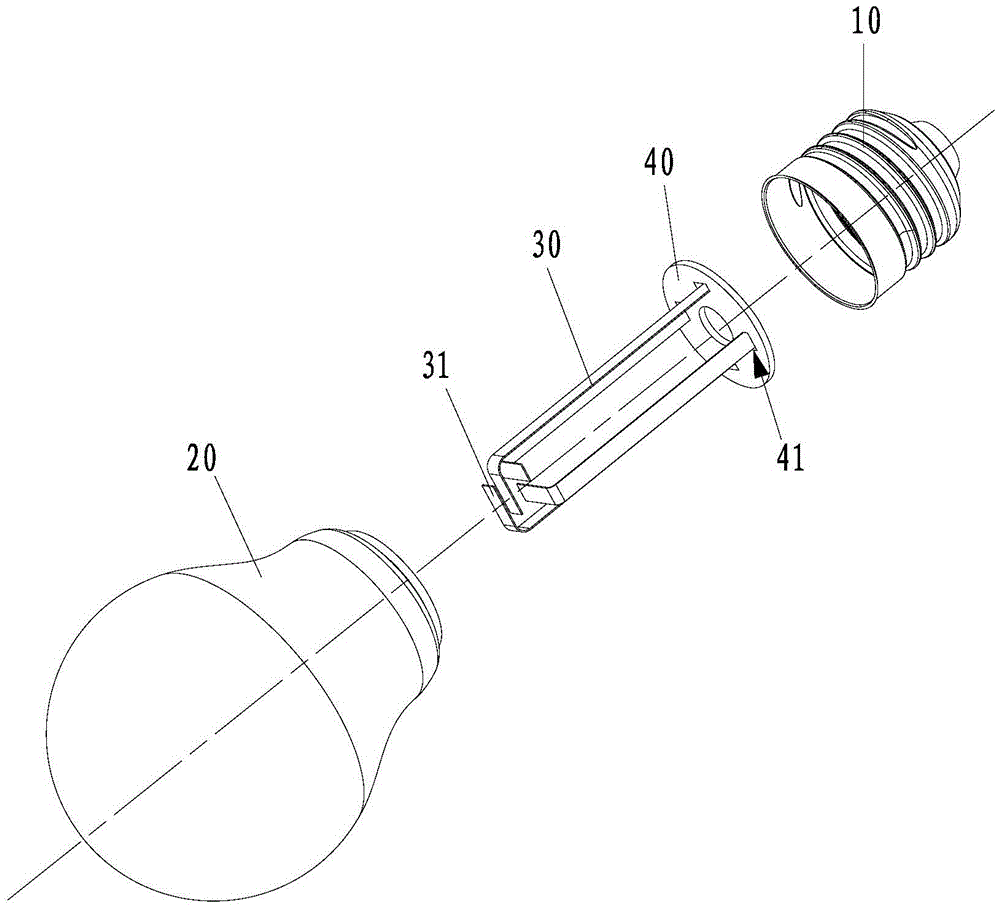
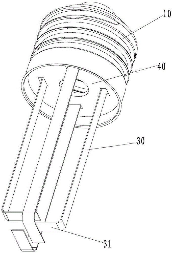
[0022] Embodiment one, consult figure 1 and figure 2 :

[0023] A kind of LED lamp, it comprises lamp base 10, lamp shell 20, drive circuit board (not shown in the figure) and light-emitting unit, light-emitting unit is placed in lamp shell 20, drive circuit board is placed in lamp base 10, lamp base 10 and lamp The housing 20 is detachably connected; the light-emitting unit includes a plurality of elongated light-emitting strips 30, which are parallel to the central axis of the lamp housing 20 and arranged at intervals around the central axis. One end of the light-emitting strips 30 is fixed to the lamp holder 10 and Connect to the driver circuit board. The light emitting strip 30 includes a carrier and LED dies, and the LED dies are evenly arranged on the carrier. In this embodiment, the carrier is in the shape of a strip. Preferably, the luminous strips include more than four, so as to ensure sufficient luminous brightness of the LED lamp.

[0024] In this embodiment, ...

Embodiment 2

[0029] The difference between the second embodiment and the first embodiment is that: the light-emitting strip is a straight strip. The light emitted by the light-emitting strips of this structure can be emitted in a 360-degree direction perpendicular to the central axis, and the brightness on the surrounding surfaces of the lamp housing is uniform, which improves the illumination brightness of the light-emitting unit; The heat dissipation space is increased, so the heat dissipation performance of the light emitting unit and the LED lamp is improved. However, there is no bare LED crystal at the end of the lamp housing away from the lamp cap, so the lack of light at the end of the lamp housing away from the lamp cap leaves a shadow position, which reduces the overall performance of the LED lamp to a certain extent.


PUM


Abstract

The invention discloses an LED (Light Emitting Diode) lamp, which comprises a lamp holder, a lamp housing, a drive circuit board and a light emitting unit, wherein the light emitting unit is arranged in the lamp housing; the drive circuit board is arranged in the lamp holder; the lamp holder is detachably connected with the lamp housing; the light emitting unit comprises a plurality of long strip-shaped light emitting bars which are parallel with the center axis of the lamp housing and are axially spaced around the center axis; and one end of each light emitting bar is fixed to the lamp holder and is electrically connected with the drive circuit board. The LED lamp has the following advantages that the brightness of light rays is uniform on the surface of the LED lamp housing; and the irradiation brightness and the radiating performance of the LED lamp are improved.

Description

technical field [0001] The invention relates to an LED lamp. Background technique [0002] In the prior art, the light-emitting unit is mostly fixed in the middle of the lamp housing. The light-emitting unit of the LED lamp includes a substrate and an LED die attached to the substrate. The LED die is distributed on one side of the substrate, and the other side of the substrate is connected to the The component is connected to the lamp holder. The side with the bare LED attached to the substrate is facing the front of the lamp housing, and the other side of the substrate is facing the lamp holder. Since the other side of the substrate is not equipped with a bare LED, the other side (the back of the bare LED) The light between the side) and the lamp head is dark, the brightness is not enough, and the light emission distribution of the light-emitting unit on the surface of the lamp housing is uneven (the brightness distribution on the surface of the lamp housing is very uneven)...

Claims


Application Information

Patent Timeline
Patent Type & Authority Applications(China)
IPC IPC(8): F21K9/232F21K9/235F21K9/238F21V19/00F21V29/503F21Y115/10
CPCF21V19/001F21V23/003
Inventor 吴鼎鼎
Owner 莆田康布斯光电科技有限公司
Why Eureka
Try Eureka