
LED lamp strip facilitating connection

A technology of LED light strips and LED lamp beads, which is applied in the parts of lighting devices, damage prevention measures of lighting devices, safety devices of lighting devices, etc. Affect the appearance of the light strip, etc., to achieve the effect of improving the illumination brightness, simple structure, and improving wear resistance

Inactive Publication Date: 2019-08-13
刘阳
View PDF0 Cites 0 Cited by
  • Summary
  • Abstract
  • Description
  • Claims
  • Application Information

AI Technical Summary

Problems solved by technology

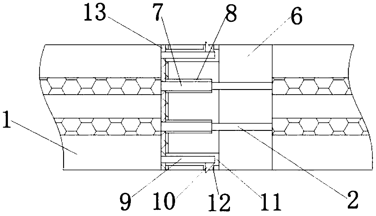
[0002] The LED light strip refers to the assembly of LEDs on a strip-shaped FPC (flexible circuit board) or PCB hard board. It is named because the product is shaped like a strip; ), and is very energy-saving and green, and gradually emerges in various decoration industries. It has the characteristics of high brightness, long service life, and eco-friendly; Due to the limited length, the light strip needs to be connected when extending and laying. The traditional light strip connection often needs to be stripped to connect the wires, and then wrapped with adhesive tape to realize the connection of the light strip. This process is more complicated and inconvenient, which is not conducive to the light strip. The rapid arrangement of the light strip affects the beauty of the laying of the light strip. There is no wire protection layer component and light-transmitting sleeve protective layer component to protect the wires inside the light strip, and the outer wall of the LED light strip is not strengthened. Long-term use is easy to cause wear and tear , affecting the service life

Method used


Image

  • LED lamp strip facilitating connection
  • LED lamp strip facilitating connection
  • LED lamp strip facilitating connection

Examples


Embodiment Construction

[0019] The following will clearly and completely describe the technical solutions in the embodiments of the present invention with reference to the accompanying drawings in the embodiments of the present invention. Obviously, the described embodiments are only some, not all, embodiments of the present invention. Based on the embodiments of the present invention, all other embodiments obtained by persons of ordinary skill in the art without making creative efforts belong to the protection scope of the present invention.

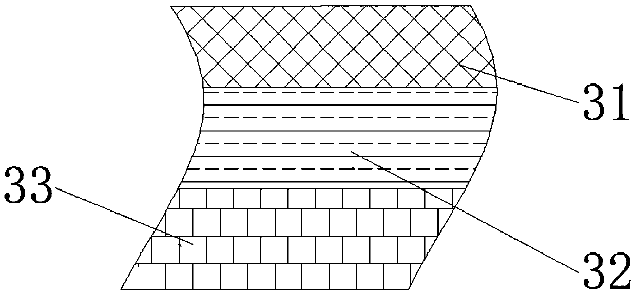
[0020] see Figure 1-4 , the present invention provides a technical solution: an LED light strip that is easy to connect, including an LED light strip main body 1, a wire 2, a wire protective layer assembly 3, a light-transmitting sleeve 4, a light-transmitting sleeve protective layer assembly 5, and a connector 6 , plug contact 7, contact slot 8, connecting rod 9, block 10, connection slot 11, bayonet 12, magnetic strip 13 and LED lamp bead 14, the interior d...


PUM


Abstract

The invention discloses an LED lamp strip facilitating connection. The LED lamp strip facilitating connection comprises an LED lamp strip main body, a wire, a wire protective layer assembly, a light transmission sleeve, a light transmission sleeve protective layer assembly, a connector, a plug-in contact, a contact plug-in groove, a connecting rod, a clamping block, a connecting groove, a bayonet,a magnetic strip and LED bulbs, wherein the LED bulbs are distributed in the LED lamp strip main body and connected with one another through the wire; and a wire protective layer assembly is arrangedoutside the wire in a sleeving manner. The LED lamp strip facilitating connection is simple in structure and convenient to use, electric connection between the two lamp strips is realized through matched connection between the plug-in contact and the contact plug-in groove, quick connection and fixation between the lamp strips are realized through cooperation of the connecting rod and the connecting groove and cooperation of the clamping block and the bayonet, and the structure is also convenient to disassemble in the later period, and secondary use in the later period is facilitated; and dueto arrangement of the wire protective layer assembly in the lamp strip, the wire has good fire resistance and external insulation.

Description

technical field [0001] The invention relates to the technical field of LED light strips, in particular to an LED light strip that is easy to connect. Background technique [0002] The LED light strip refers to the assembly of LEDs on a strip-shaped FPC (flexible circuit board) or PCB hard board. It is named because the product is shaped like a strip; ), and is very energy-saving and green, and gradually emerges in various decoration industries. It has the characteristics of high brightness, long service life, and eco-friendly; Due to the limited length, the light strip needs to be connected when extending and laying. The traditional light strip connection often needs to be stripped to connect the wires, and then wrapped with adhesive tape to realize the connection of the light strip. This process is more complicated and inconvenient, which is not conducive to the light strip. The rapid arrangement of the light strip affects the beauty of the laying of the light strip. There...

Claims


Application Information

Patent Timeline
Patent Type & Authority Applications(China)
IPC IPC(8): F21S4/24F21V23/06F21V25/00F21V15/00F21V19/00F21Y115/10
CPCF21S4/24F21V15/00F21V19/0025F21V23/06F21V25/00F21Y2115/10
Inventor 刘阳
Owner 刘阳
Learn More