
Rotary shaft assembly and displayer or television

A technology for monitors and televisions, applied in the direction of pivots, pivot connections, shafts and bearings, etc., can solve problems such as damage, limited support capacity, poor structure around the shaft structure, etc., and achieve the effect of avoiding damage and avoiding the phenomenon of bowing

Active Publication Date: 2016-04-13
HEFEI HUIKE JINYANG TECH
View PDF6 Cites 0 Cited by
  • Summary
  • Abstract
  • Description
  • Claims
  • Application Information

AI Technical Summary

Problems solved by technology

Therefore, within a certain range of rotation angles, when the torsion force of this type of shaft structure is small, its supporting capacity is limited, and the supported display screen is heavy, and it is prone to bowing phenomenon, that is, the torque force of the shaft structure is not enough to support the display screen. weight, which causes the display screen to automatically rotate downward under its own gravity; when the torsion of such a rotating shaft structure is large, it will cause poor or even damage to the surrounding structures of the rotating shaft structure due to rotation

Method used


Image

  • Rotary shaft assembly and displayer or television
  • Rotary shaft assembly and displayer or television
  • Rotary shaft assembly and displayer or television

Examples


Embodiment Construction

[0021] In order to make the object, technical solution and advantages of the present invention clearer, the present invention will be further described in detail below in conjunction with the accompanying drawings and embodiments. It should be understood that the specific embodiments described here are only used to explain the present invention, not to limit the present invention.

[0022] It should be noted that when an element is referred to as being “fixed on” or “disposed on” another element, it may be directly on the other element or there may be an intervening element at the same time. When an element is referred to as being "connected to" another element, it can be directly connected to the other element or intervening elements may also be present.

[0023] In addition, it should be noted that the orientation terms such as left, right, up, and down in the embodiments of the present invention are only relative concepts or refer to the normal use state of the product, and...


PUM


Abstract

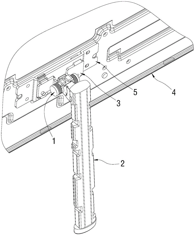
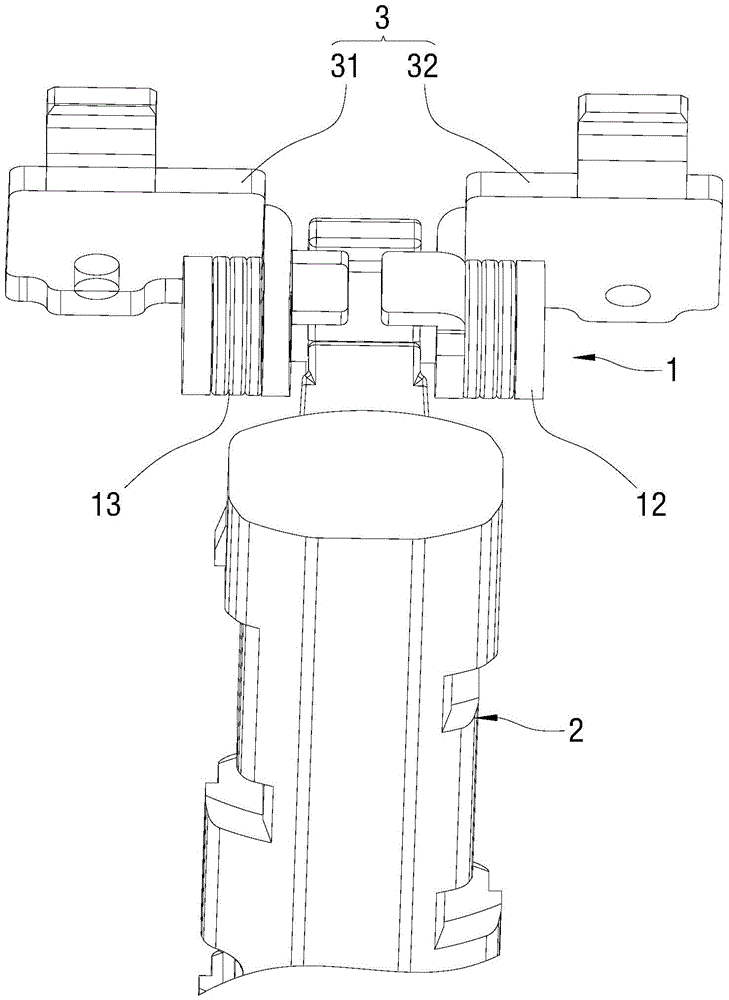
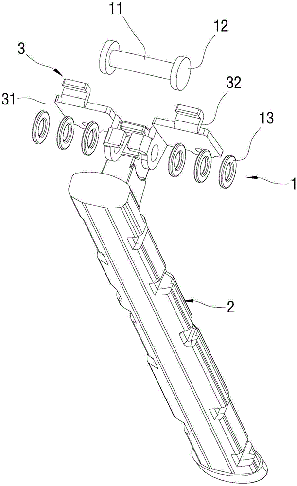
The invention relates to the technical field of rotary shaft structures and discloses a rotary shaft assembly and a displayer or a television. The rotary shaft assembly is used for rotationally connecting a supporting column and a connector of the displayer or the television and comprises a rotary shaft axially and movably penetrating through the supporting column and the connector, shaft caps arranged at two ends of the rotary shaft and multiple washers which sleeve the rotary shaft and are abutted between each shaft cap and the connector, wherein a bulged resistance mechanism used for adjusting relative rotation torsion of the supporting column and the connector is arranged on the side surface of each washer, and two resistance mechanisms on every two adjacent washers are abutted against each other. According to the rotary shaft assembly and the displayer or the television, the rotary shaft is sleeved with multiple washers abutted between each shaft cap and the connector, the bulged resistance mechanism is arranged on the side surface of each washer, the two resistance mechanisms on every two adjacent washers are abutted against each other, accordingly, when the supporting column rotates relative to the connector, relative rotation torsion adjustment of the supporting column and the connector is realized under the resistance function of the resistance mechanisms, and the phenomenon that the displayer droops is avoided.

Description

technical field [0001] The invention relates to the technical field of a rotating shaft structure, in particular to a rotating shaft assembly and a display or a television. Background technique [0002] In existing monitors or televisions, the display screen and the base assembly are usually rotatably connected through a rotating shaft structure. However, in practical applications, the torsional force of such a rotating shaft structure is constant. Therefore, within a certain range of rotation angles, when the torsion force of this type of shaft structure is small, its supporting capacity is limited, and the supported display screen is heavy, and it is prone to bowing phenomenon, that is, the torque force of the shaft structure is not enough to support the display screen. The weight causes the display screen to automatically rotate downward under its own gravity; when the torsion of such a rotating shaft structure is large, it will cause poor or even damage to the surroundi...

Claims


Application Information

Patent Timeline
Patent Type & Authority Applications(China)
IPC IPC(8): F16M11/10F16C11/04F16C11/10
CPCF16C11/04F16C11/103F16M11/10
Inventor 王智勇郭湘波葛兴
Owner HEFEI HUIKE JINYANG TECH
Learn More