Supercharge Your Innovation With Domain-Expert AI Agents!

Driving mechanism and injection device with driving mechanism

A driving mechanism and injection device technology, applied in the direction of automatic injectors, syringes, ampoule syringes, etc., can solve problems such as user confusion of pharmaceutical devices

Inactive Publication Date: 2020-10-02
SANOFI SA
View PDF10 Cites 0 Cited by
  • Summary
  • Abstract
  • Description
  • Claims
  • Application Information

AI Technical Summary

Problems solved by technology

A potential disadvantage of known injection devices is the effect of play within the mechanism, as a result of manufacturing tolerances or assembly design, which can cause the piston rod to advance slightly when the device is dialed to obtain a subsequent dose, while dispensing potion
In other words, "dripping" may occur during dose setting, which is undesirable due to loss of medicament and potential confusion for the device user

Method used


Image

  • Driving mechanism and injection device with driving mechanism
  • Driving mechanism and injection device with driving mechanism
  • Driving mechanism and injection device with driving mechanism

Examples


Embodiment Construction

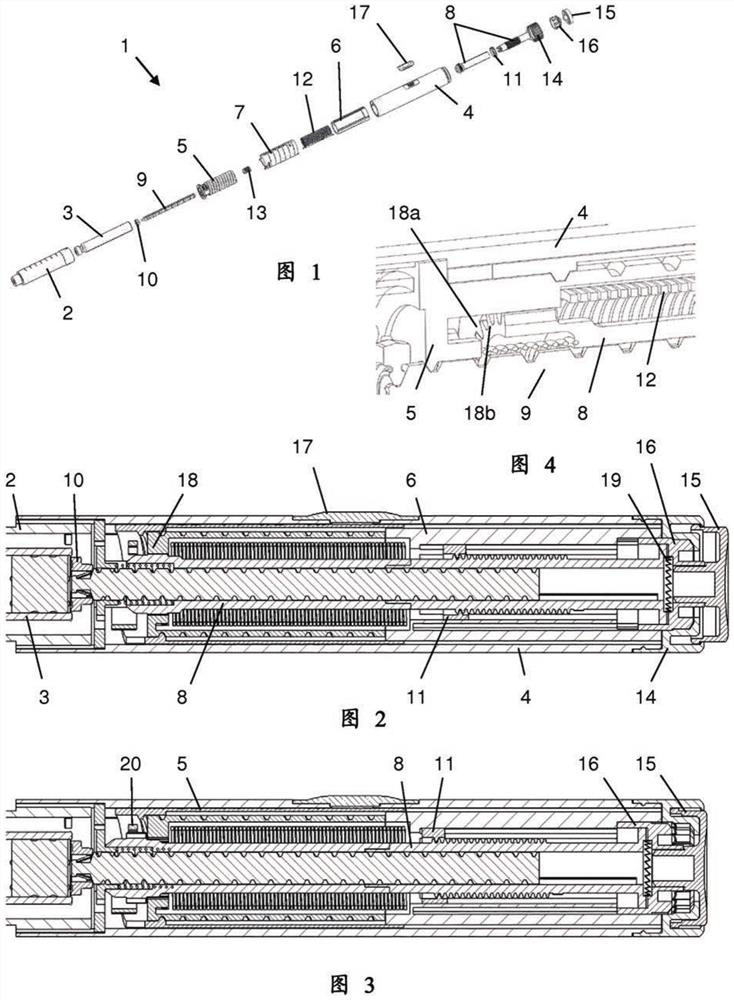
[0113] The injection device 1 according to the invention is figure 1 shown in an exploded view. The injection device 1 comprises a cartridge holder 2, a cartridge 3 and a drive mechanism. The drive mechanism includes an outer housing 4, an inner housing 5, a dose dial sleeve as a dial member 6, a digital sleeve as a display member 7, a drive sleeve as a drive member assembly 8, a lead screw 9, a bearing 10, Nut 11 , drive spring 12 , return spring 13 , dial handle 14 , dose button 15 and clutch plate 16 . All components are concentrically located about a common main axis of the mechanism. In more detail, the drive member assembly 8 surrounds the lead screw 9, the torsion spring 12 surrounds the drive member 8, the dial member 6 and inner housing 4 surround the torsion spring 12, the display member 7 surrounds the dial member 6, and the outer housing 4 surrounds the display Component 7. Furthermore, the nut 11 and the clutch plate 16 are located between the drive member ass...


PUM


Abstract

A drive mechanism suitable for an injection device includes a housing, a piston rod at least axially movable relative to the housing, and a drive member which is coupled to the housing via a first clutch such that a relative rotation of the drive member about an axis of rotation with respect to the housing is prevented during dose setting and is allowed during dose dispensing. The drive member engages the piston rod such that a rotation of the drive member causes an axial movement of the piston rod. Re-engagement of the first clutch causes rotation of the drive member with respect to the housing in a direction moving the piston rod in the proximal direction.

Description

technical field [0001] The present invention relates to a drive mechanism suitable for use in injection devices, especially pen-type drug delivery devices. The mechanism includes: a housing; a piston rod movable at least axially relative to the housing; and a drive member coupled to the housing via a first clutch to enable relative rotation of the drive member with respect to the housing about an axis of rotation Blocked during dose setting and enabled during dose dispense. Preferably, the drive member engages the piston rod such that rotation of the drive member causes axial movement of the piston rod. Furthermore, the invention relates to an injection device comprising such a drive mechanism and a cartridge containing a medicament. Background technique [0002] In the following, the distal end of the injection device or the drive mechanism is referred to as the end where the reservoir and eg the needle are located, while the opposite end is the proximal end. A dose butt...

Claims


Application Information

Patent Timeline
Patent Type & Authority Patents(China)
IPC IPC(8): A61M5/20A61M5/315A61M5/24A61M5/31A61M5/32
CPCA61M5/20A61M5/3148A61M5/31535A61M5/31541A61M5/31553A61M5/3157A61M5/31578A61M5/31583A61M5/3202A61M2005/2073A61M2205/581A61M2205/582A61M2005/2026
Inventor D·A·普伦特里S·L·比尔顿
Owner SANOFI SA
Features
  • R&D
  • Intellectual Property
  • Life Sciences
  • Materials
  • Tech Scout
  • Unparalleled Data Quality
  • Higher Quality Content
  • 60% Fewer Hallucinations
Learn More