
A special fixture and clamping method for CNC machining bending parts

A technology for special fixtures and bending parts, applied to metal processing machinery parts, manufacturing tools, metal processing equipment, etc., can solve problems such as difficult positioning, workpiece deformation, and time-consuming

Active Publication Date: 2018-05-04
强龙科技(苏州)有限公司
View PDF8 Cites 0 Cited by
  • Summary
  • Abstract
  • Description
  • Claims
  • Application Information

AI Technical Summary

Problems solved by technology

The defects of this type are: for the processing of curved parts, multiple sets of fixtures are required for multiple clamping to complete the processing, because the processing of curved parts is difficult, and the use of traditional fixtures requires a little bit of clamping, which is cumbersome and time-consuming. When clamping, it is easy to cause deformation of the workpiece, it is not easy to locate, the deviation of the processing size is large, it is very unstable, and it affects the processing accuracy

Method used


Image

  • A special fixture and clamping method for CNC machining bending parts
  • A special fixture and clamping method for CNC machining bending parts
  • A special fixture and clamping method for CNC machining bending parts

Examples


Embodiment Construction

[0020] Embodiments of the present invention are described in detail below, examples of which are shown in the drawings, wherein the same or similar reference numerals designate the same or similar elements or elements having the same or similar functions throughout. The embodiments described below by referring to the figures are exemplary only for explaining the present invention and should not be construed as limiting the present invention.

[0021] In the description of the present invention, unless otherwise specified and limited, it should be noted that the terms "installation", "connection" and "connection" should be understood in a broad sense, for example, it can be mechanical connection or electrical connection, or two The internal communication of a component can be directly connected or indirectly connected through an intermediary. Those of ordinary skill in the art can understand the specific meanings of the above terms according to specific situations.

[0022] Re...


PUM


Abstract

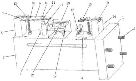
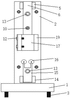
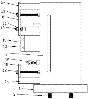
A special clamp for machining of bent parts comprises a chassis and a clamp main board, wherein the chassis is arranged on the lateral face of the clamp main board; the chassis and the clamp main board are integrally molded; a plurality of positioning screws penetrate through the chassis from left to right; the clamp is installed on a machine tool through the positioning screws in the machining process; the whole clamp main board is a cuboid; the upper surface of the clamp main board is the machining base plane; the base plane is provided with a left positioning unit, a right positioning unit and a fixing unit; the left positioning unit and the right positioning unit are arranged on the left side and the right side of the base plane respectively; the fixing unit is arranged between the left positioning unit and the right positioning unit. The overall design and the positioning modes of the clamp are adjusted, and the deformability of workpieces is controlled; multiple faces can be machined at a time by many angles, short time is consumed, and the machining precision and production efficiency are improved.

Description

technical field [0001] The invention relates to the field of mechanical manufacturing, in particular to a special fixture and a clamping method for CNC machining bending parts. Background technique [0002] The earlier fixture type is mainly composed of moving jaws and fixed jaws, and the type is relatively simple. The defects of this type are: for the processing of curved parts, multiple sets of fixtures are required for multiple clamping to complete the processing, because the processing of curved parts is difficult, and the use of traditional fixtures requires a little bit of clamping, which is cumbersome and time-consuming. When clamping, it is easy to cause deformation of the workpiece, it is not easy to locate, the deviation of the processing size is large, it is very unstable, and it affects the processing accuracy. Contents of the invention [0003] The invention aims to provide a special fixture and clamping method for processing curved parts that can control the...

Claims


Application Information

Patent Timeline
Patent Type & Authority Patents(China)
IPC IPC(8): B23Q3/06
CPCB23Q3/062
Inventor 陈锐杰
Owner 强龙科技(苏州)有限公司
Learn More