Computer-room device support
A technology for equipment support and machine room, which is applied in the direction of mechanical equipment, machine platform/support, supporting machine, etc., which can solve the problems of inconvenient cable removal, limited floor space, and small space in the machine room, and achieve the effect of convenient wiring operation
- Summary
- Abstract
- Description
- Claims
- Application Information
AI Technical Summary
Problems solved by technology
Method used
Image
Examples
Embodiment 1
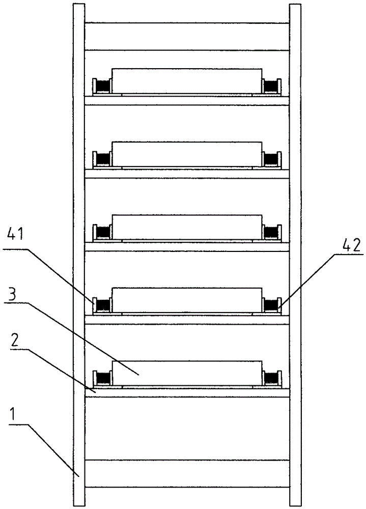
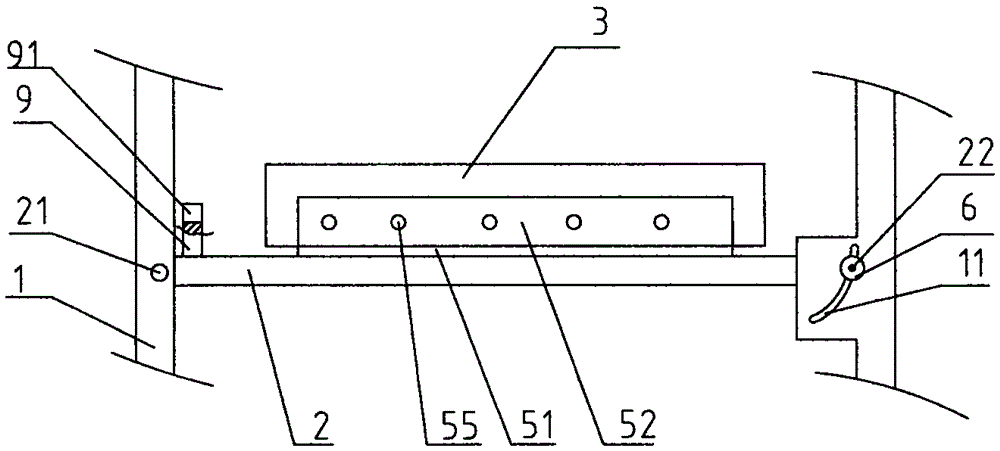
[0027] refer to figure 1 and figure 2 , a machine room equipment bracket shown, including a frame 1, on which support plates 2 are arranged at intervals along the height direction, machine room equipment 3 is placed on the support plates 2, and the rear end of the support plate 2 is provided with a rotating shaft 21 , the rotating shaft 21 is rotatably connected with the frame 1, and the front end of the support plate 2 is flexibly connected with the frame 1, so the support plate 2 can be turned around the support plate 2, and after the front end of the support plate 2 is turned downward, it is convenient for the operator to The rear end of the equipment room 3 performs wiring operations.
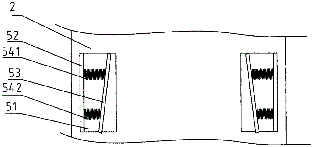
[0028] During the overturning process of the support plate 2, in order to prevent the machine room equipment 3 from slipping off the support plate 2, elastic clip arms for clamping the machine room equipment 3 are arranged on the support plate 2. The left clamping arm 41 and the right cl...
Embodiment 2
[0037] A support for machine room equipment, including a frame, on which support plates are arranged at intervals along the height direction, equipment in the machine room is placed on the support plates, and the rear end of the support plates is provided with a rotating shaft, which is rotatably connected to the frame, and the support plates The front end is movably connected with the frame, so the support plate can be flipped around the support plate, and the elastic clamp arm for clamping the equipment in the computer room is set on the support plate. The elastic clamp arm includes the left clamp arm and the right clamp arm on both sides of the equipment room The jig arm, the machine room equipment is clamped between the left jig arm and the right jig arm. Slide blocks are arranged on both sides of the front end of the support plate, arc-shaped guide grooves connecting the slide blocks are provided on the frame, and a positioning mechanism for positioning the slide block is ...
Embodiment 3
[0039] A support for machine room equipment, including a frame, on which support plates are arranged at intervals along the height direction, equipment in the machine room is placed on the support plates, and the rear end of the support plates is provided with a rotating shaft, which is rotatably connected to the frame, and the support plates The front end is movably connected with the frame, so the support plate can be flipped around the support plate, and the elastic clamp arm for clamping the equipment in the computer room is set on the support plate. The elastic clamp arm includes the left clamp arm and the right clamp arm on both sides of the equipment room The clamping arm, the machine room equipment is clamped between the left clamping arm and the left clamping arm. refer to Figure 5 The difference between this embodiment and Embodiment 1 is that: the rear end of the frame 1 is provided with a movable groove 13 connecting the rotating shaft 21, the movable groove 13 ex...
PUM
 Abstract
Description
Claims
Application Information
 - R&D
- Intellectual Property
- Life Sciences
- Materials
- Tech Scout
- Unparalleled Data Quality
- Higher Quality Content
- 60% Fewer Hallucinations
Browse by: Latest US Patents, China's latest patents, Technical Efficacy Thesaurus, Application Domain, Technology Topic, Popular Technical Reports.
© 2025 PatSnap. All rights reserved.Legal|Privacy policy|Modern Slavery Act Transparency Statement|Sitemap|About US| Contact US: help@patsnap.com


