
Air conditioning device air outlet structure and air conditioning device

A technology for air-conditioning equipment and air outlets, which is applied in the air-out structure of air-conditioning equipment and the field of air-conditioning equipment, which can solve problems such as single air supply direction, slow cooling and heating speed, and insufficient air volume, so as to increase the overall area and improve comfort Feel and increase the effect of wide-angle air supply

Inactive Publication Date: 2016-04-20
GREE ELECTRIC APPLIANCES INC
View PDF6 Cites 12 Cited by
  • Summary
  • Abstract
  • Description
  • Claims
  • Application Information

AI Technical Summary

Problems solved by technology

[0003] In addition, the sweeping blades basically play an auxiliary role in adjusting the horizontal air supply angle. Although some air-conditioning equipment can achieve an air supply angle of 120° left and right at this stage, there will still be dead air supply angles on the left and right sides of the air outlet. , which restricts the further increase of the air supply angle. This shortcoming may cause the air conditioner to slow down the cooling and heating speed of the room, the air supply direction is single, and the adjustable range is small.
In addition, there may be shortcomings such as insufficient air supply stability, insufficient air volume, and insufficient filling room area.
Since the direction of the air outlet of the air conditioner and the stability of the air supply will directly affect the distribution of the temperature field, these factors may lead to uneven distribution of the indoor temperature field, which cannot bring users a better sense of comfort

Method used


Image

  • Air conditioning device air outlet structure and air conditioning device
  • Air conditioning device air outlet structure and air conditioning device
  • Air conditioning device air outlet structure and air conditioning device

Examples


Embodiment Construction

[0022] The present invention will be described in detail below. In the following paragraphs, different aspects of the embodiments are defined in more detail. Aspects so defined may be combined with any other aspect or aspects unless specifically stated otherwise. In particular, any feature considered to be preferred or advantageous may be combined with one or more other features which are considered to be preferred or advantageous.

[0023] Terms such as "first" and "second" appearing in the present invention are only for convenience of description, to distinguish different components with the same name, and do not indicate a sequence or a primary and secondary relationship.

[0024] In the description of the present invention, considering that the air outlet is generally elongated, terms such as "length", "width" and "height" are used in the description based on this air outlet. In addition, "on", " The orientations or positional relationships indicated by "down", "left" an...


PUM


Abstract

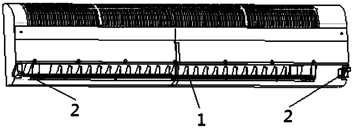
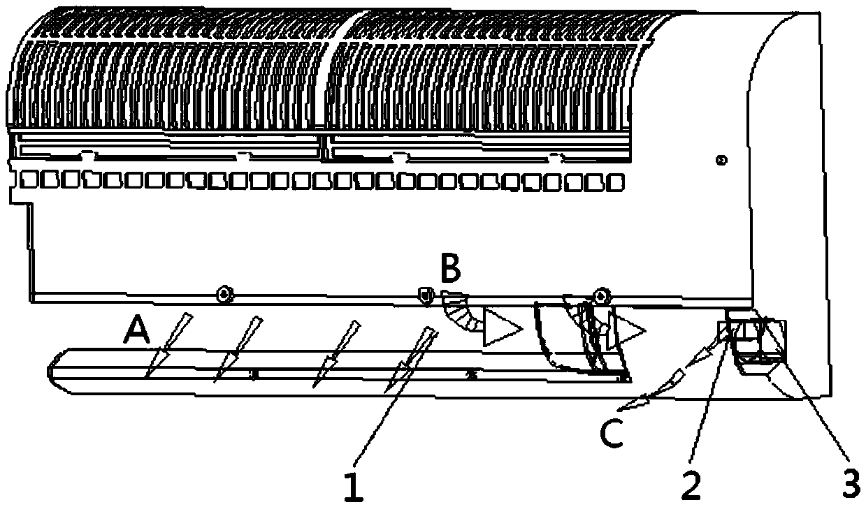
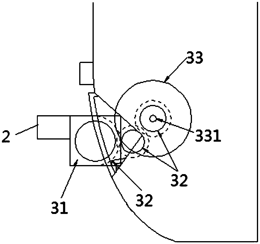
The invention relates to an air conditioning device air outlet structure and an air conditioning device. The air conditioning device air outlet structure comprises an air outlet and fan assemblies, wherein the air outlet comprises a main air outlet and auxiliary air outlets, the main air outlet is the portion, opposite to fan blades of the air conditioning device, of the air outlet, the auxiliary air outlets are the portions of the air outlet except the main air outlet, and an air outlet of the fan assemblies are adjacent to the auxiliary air outlets and are used for guiding airflows in the air conditioning device to the auxiliary air outlets so as to enable the auxiliary air outlets and the main air outlet to jointly perform air output. The air conditioning device air outlet structure can increase a wide air supply angle and enables dead corner areas on the left side and the right side of the air conditioning device to be capable of performing air supply. In addition, simultaneous air supply in multiple directions can be achieved, and accordingly the speed of enabling a room to be full of air can be improved. Furthermore, due to the whole area increase of the air outlet, air supply uniformity can be improved and air speed can be reduced under the condition that the air supply volume is definite so as to improve the comfort feeling of a user.

Description

technical field [0001] The invention relates to the technical field of air-conditioning equipment, in particular to an air outlet structure of the air-conditioning equipment and the air-conditioning equipment. Background technique [0002] The air outlet of the traditional wall-mounted air conditioner is generally set at the lower part of the casing, and an air deflector can be installed at the air outlet. When the air conditioner is working, the air outlet can be controlled by the air deflector. For example: when cooling The air is blown toward the ground, and the air is blown horizontally when heating. [0003] In addition, the sweeping blades basically play an auxiliary role in adjusting the horizontal air supply angle. Although some air-conditioning equipment can achieve an air supply angle of 120° left and right at this stage, there will still be dead air supply angles on the left and right sides of the air outlet. , which restricts the further increase of the air supp...

Claims


Application Information

Patent Timeline
IPC IPC(8): F24F13/14
CPCF24F13/10F24F13/14
Inventor 孟智李芊梁涛谢承琪
Owner GREE ELECTRIC APPLIANCES INC
Learn More