
Wall-mounted air conditioner indoor unit

A technology for wall-mounted air conditioners and indoor units, which is applied in air-conditioning systems, heating methods, space heating and ventilation, etc., and can solve problems such as the complex structure of wall-mounted air conditioner indoor units, the complex structure of centrifugal fan air ducts, and large operating noises. Achieve the effects of improving user experience, increasing the wide angle of air supply, and increasing the air supply volume

Pending Publication Date: 2018-11-06
QINGDAO HAIER AIR CONDITIONER GENERAL CORP LTD
View PDF0 Cites 4 Cited by
  • Summary
  • Abstract
  • Description
  • Claims
  • Application Information

AI Technical Summary

Problems solved by technology

However, a single axial flow fan or centrifugal fan cannot meet the normal air supply demand, and multiple axial flow fans or centrifugal fans need to be installed, and the axial flow fan has strict requirements on the position of the air inlet, and the air duct of the centrifugal fan The structure is relatively complex and takes up space, which leads to the structure of this type of wall-mounted air conditioner indoor unit is very complicated, the volume is relatively large, and the operating noise is relatively loud

Method used


Image

  • Wall-mounted air conditioner indoor unit
  • Wall-mounted air conditioner indoor unit
  • Wall-mounted air conditioner indoor unit

Examples


Embodiment Construction

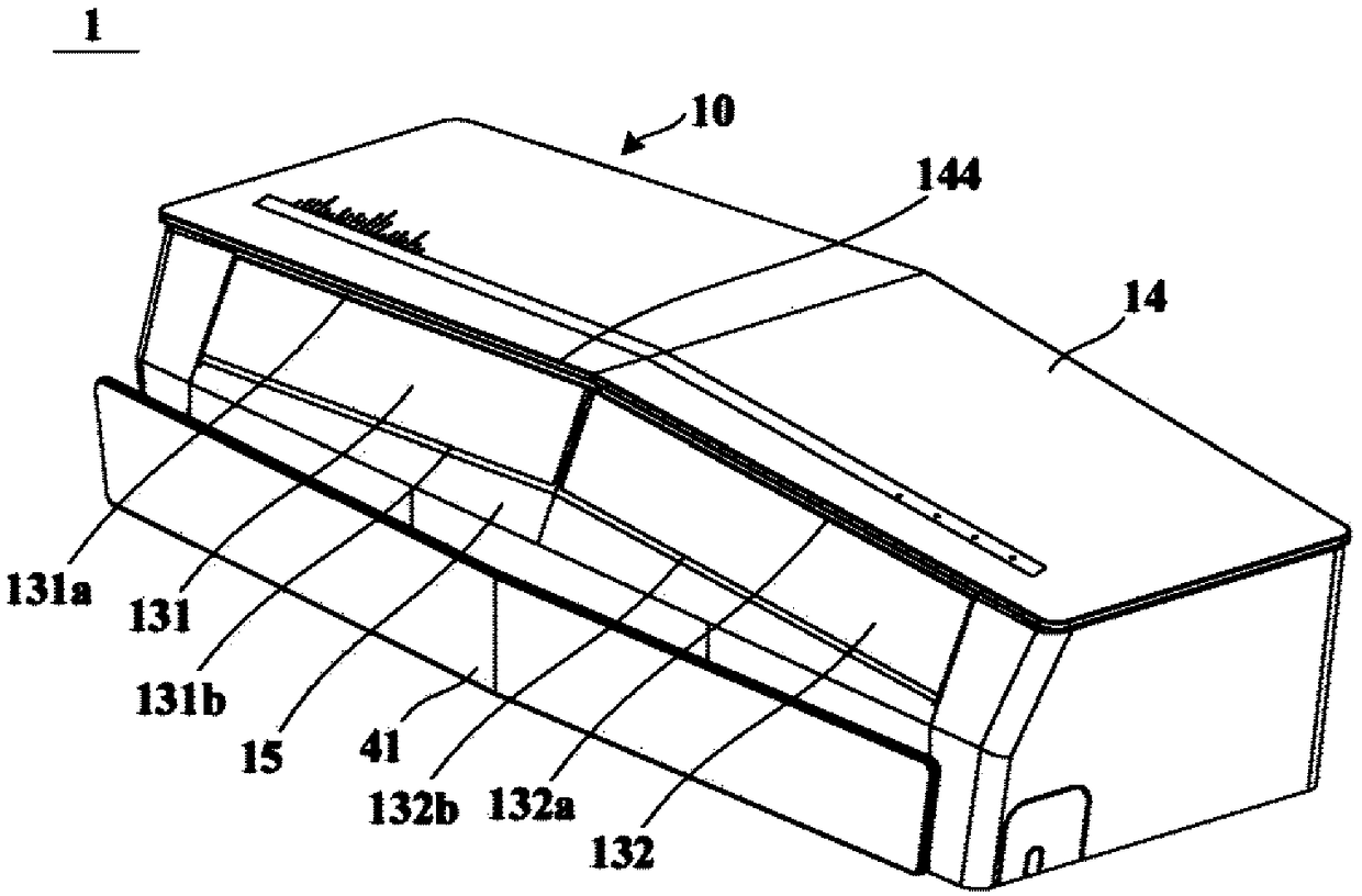
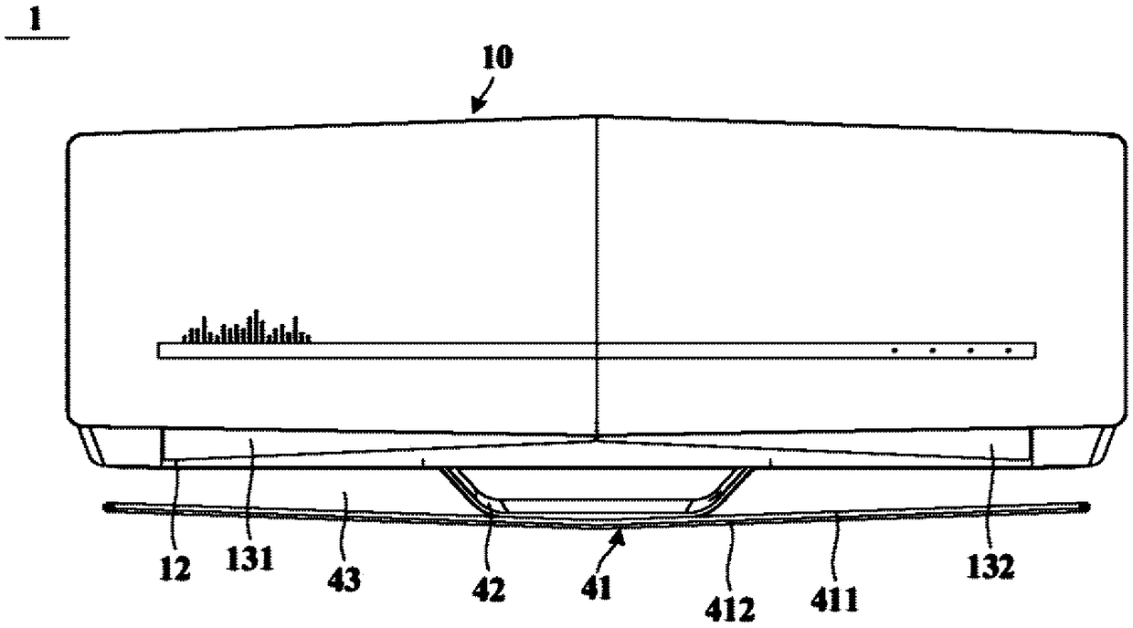
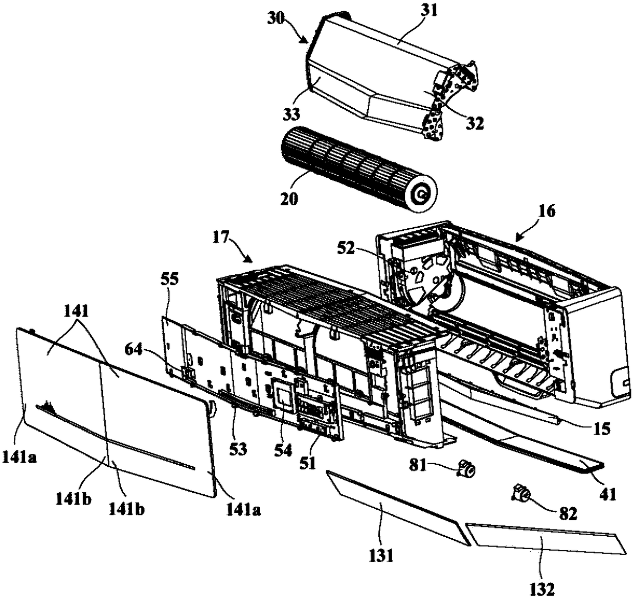
[0043] The invention provides a wall-mounted air conditioner indoor unit, figure 1 is a schematic structural diagram of a wall-mounted air conditioner indoor unit according to an embodiment of the present invention, figure 2 is a schematic front view of a wall-mounted air conditioner indoor unit according to an embodiment of the present invention, image 3 is a schematic exploded view of a wall-mounted air conditioner indoor unit according to an embodiment of the present invention, Figure 4 It is a schematic sectional view taken along a horizontal plane of a wall-mounted air conditioner indoor unit according to an embodiment of the present invention.

[0044] see Figure 1 to Figure 4 , the wall-mounted air conditioner indoor unit 1 of the present invention includes a casing 10 and at least one cross-flow fan 20 and an evaporator 30 disposed in the casing 10 . The casing 10 is used to constitute the casing of the wall-mounted air conditioner indoor unit 1 . The evaporato...


PUM


Abstract

The invention relates to a wall-mounted air conditioner indoor unit. The wall-mounted air conditioner indoor unit comprises a machine shell, at least one cross-flow fan and an evaporator; the machineshell is provided with an air inlet and an air outlet, two independent air guide plates are arranged at the air outlet, and each air guide plate is configured to be controlled to be pivoted around a rotating shaft of the corresponding air guide plate; the at least one cross-flow fan and the evaporator are arranged in the machine shell, the evaporator is arranged on the at least one cross-flow fanin a covering mode, and comprises a first heat exchange section, a second heat exchange section and a third heat exchange section which are sequentially connected from back to front, and the third heat exchange section is a V-shaped heat exchange section which extends gradually obliquely in the direction opposite to the outer side of the at least one cross-flow fan from the transverse two ends ofthe machine shell to the middle of the machine shell or a curved surface heat exchange section which gradually protrudes and extends in a bending mode in the direction towards the outer side. Rotatingshafts of the two air guide plates extend upwards from the two transverse side parts of the machine shell to the middle part of the machine shell correspondingly so as to enable the projection of therotating shafts of the two air guide plates in the vertical plane perpendicular to the front and back direction to form an inverted V shape which is gradually obliquely upwards from the transverse two ends of the machine shell to the middle of the machine shell.

Description

technical field [0001] The invention relates to an air conditioner, in particular to a wall-mounted air conditioner indoor unit. Background technique [0002] In order to save space, household appliances such as air conditioners are increasingly miniaturized, but users have higher and higher requirements for air supply performance, aesthetic appearance and many other aspects. The traditional wall-mounted air conditioner indoor unit has a single appearance, and the limitation of shape change limits the improvement of air conditioner performance to a certain extent. [0003] The wall-mounted air-conditioning indoor units in the prior art usually use a combination of swing blades and air deflectors to guide the air outlet to supply air. The rotating shaft swings left and right, thereby adjusting the air supply direction of the air outlet in the up-down direction and left-right direction. However, due to the limitation of the casing structure, the swing range of the wind defle...

Claims


Application Information

Patent Timeline
IPC IPC(8): F24F1/00F24F13/14F24F13/20F24F13/24F24F13/30
CPCF24F1/0025F24F13/1413F24F13/1426F24F13/20F24F13/24F24F13/30F24F2013/1433F24F2013/205F24F2013/247
Inventor 刘光朋
Owner QINGDAO HAIER AIR CONDITIONER GENERAL CORP LTD
Learn More