Pneumatic chuck for laser cutting machine

A technology of laser cutting machine and pneumatic chuck, which is applied in the direction of laser welding equipment, welding equipment, metal processing equipment, etc., can solve the problems of inconvenient clamping size, easy to clamp damaged products, low production efficiency, etc., and achieve clamping products Firm and reliable, avoiding damage to products, and improving production efficiency

Active Publication Date: 2016-04-27
SUZHOU QUICK LASER TECH
View PDF7 Cites 8 Cited by
  • Summary
  • Abstract
  • Description
  • Claims
  • Application Information

AI Technical Summary

Problems solved by technology

[0002] Laser cutting machine is a commonly used product cutting equipment. Existing laser cutting machines usually include chucks for fixing products. The existing chucks are ordinary three-jaw chucks. It is extremely difficult to clamp products of different sizes. Inconvenient, you have to loosen a lot to load and unload the product, and manual operation is required, the labor intensity is quite high, the production efficiency is very low, and the clamping force of the chuck is completely controlled by manpower, it is not easy to control, and it is easy to pinch the product

Method used


Image

  • Pneumatic chuck for laser cutting machine
  • Pneumatic chuck for laser cutting machine
  • Pneumatic chuck for laser cutting machine

Examples


Embodiment Construction

[0027] The present invention will be further described below in conjunction with specific embodiments.

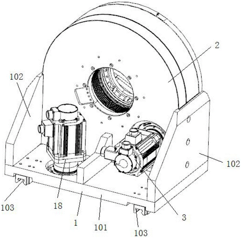
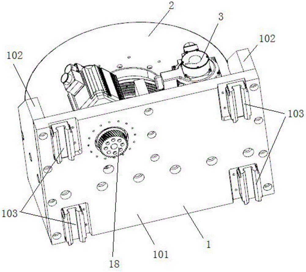
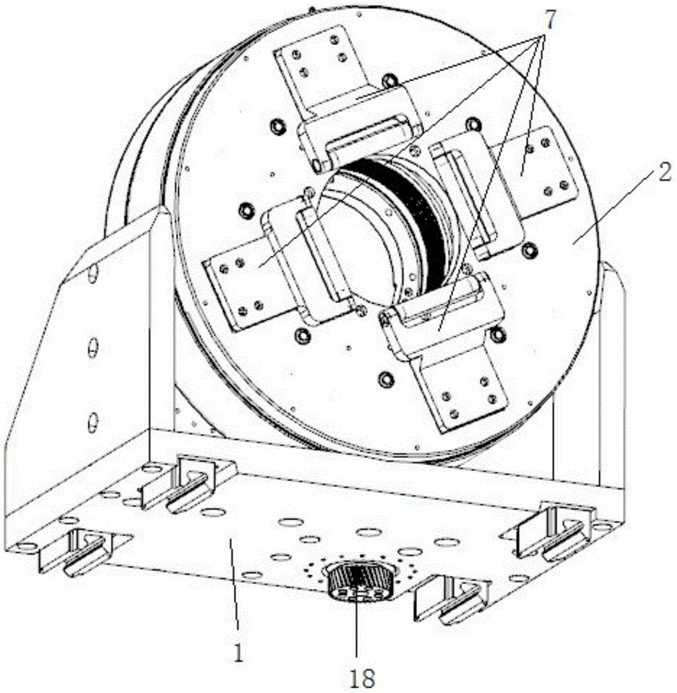
[0028] see Figure 1 to Figure 10 As shown, the present invention provides a pneumatic chuck for a laser cutting machine, including a base 1 and a clamping device, the clamping device is installed on the top of the base 1, and the clamping device includes a housing 2 and a first motor 3. A first gear 4 is installed on the first motor 3, and the first gear 4 extends into the casing 2, and the casing 2 is provided with a first mounting plate 5 inside, and the first mounting plate 5 A second gear 6 is fixed on the outer wall, and the second gear 6 meshes with the first gear 4; the clamping device also includes at least two groups of claws 7, a second mounting plate 8, a cylinder 9, a third mounting Disk 10 and first transmission mechanism 11, the third installation disk 10 is connected with the first installation disk 5, the second installation disk 8 is connected with the th...


PUM


Abstract

The invention discloses a pneumatic chuck for a laser cutting machine. The pneumatic chuck for the laser cutting machine comprises a base and a clamping device. The clamping device comprises a shell and a first motor. A first gear is installed on the first motor. A first installation disc is arranged in the shell. A second gear is fixed to the first installation disc and engaged with the first gear. The clamping device further comprises at least two sets of clamping jaws, a second installation disc, an air cylinder, a third installation disc and a first transmission mechanism. The first installation disc, the third installation disc and the second installation disc are connected in sequence. The clamping jaws and the first transmission mechanism are installed on the side, backing onto the third installation disc, of the second installation disc. The air cylinder is installed on the side, backing onto the second installation disc, of the third installation disc. The first transmission mechanism is connected with the clamping jaws and the air cylinder. According to the pneumatic chuck for the laser cutting machine, the clamping jaws can be controlled by the air cylinder to clamp a product, and the product is prevented from being damaged by adjusting the clamping force; the first motor can drive the clamping device to rotate for position adjustment; the second motor can drive the pneumatic chuck to move on a machine tool; manual operation is not needed in the whole process, and the production efficiency is improved.

Description

technical field [0001] The invention relates to a pneumatic chuck for a laser cutting machine. Background technique [0002] Laser cutting machine is a commonly used product cutting equipment. Existing laser cutting machines usually include chucks for fixing products. The existing chucks are ordinary three-jaw chucks. It is extremely difficult to clamp products of different sizes. It is inconvenient, it needs to be loosened a lot to load and unload the product, and manual operation is required, the labor intensity is quite high, the production efficiency is very low, and the clamping force of the chuck is completely controlled by manpower, it is not easy to control, and it is easy to clamp the product. Therefore, it is necessary to provide a new chuck to solve the above problems. Contents of the invention [0003] The object of the present invention is to provide a pneumatic chuck for a laser cutting machine that can automatically clamp a product, facilitate control of th...

Claims


Application Information

Patent Timeline
IPC IPC(8): B23K26/38B23K26/70
CPCB23K26/38
Inventor 颜章健
Owner SUZHOU QUICK LASER TECH
Why Eureka
Try Eureka