Rotor shaft end locking device and method

A technology for locking devices and rotor shafts, applied in workpiece clamping devices, manufacturing tools, etc., can solve problems affecting the performance of servo motors, affecting the quality of rotor shafts, and damage to the surface of rotor shafts, so as to ensure performance, protect surface quality, The effect of improving efficiency

Active Publication Date: 2016-04-27
安吉桢正运动控制技术有限公司
View PDF9 Cites 0 Cited by
  • Summary
  • Abstract
  • Description
  • Claims
  • Application Information

AI Technical Summary

Problems solved by technology

[0003] The invention mainly solves the technical problem that the original motor rotor shaft clamping equipment is inconvenient to disassemble, takes time and effort, and will still damage the surface of the rotor shaft, which will affect the quality of the rotor shaft and further affect the performance of the servo motor; it provides a A rotor shaft end locking device and a locking method thereof, which can easily and repeatedly disassemble and assemble the rotor shaft, save time and effort, improve efficiency, and can ensure that the surface of the rotor shaft is not damaged, protect the surface quality of the rotor shaft, and thus ensure the servo motor performance

Method used


Image

  • Rotor shaft end locking device and method
  • Rotor shaft end locking device and method
  • Rotor shaft end locking device and method

Examples


Embodiment

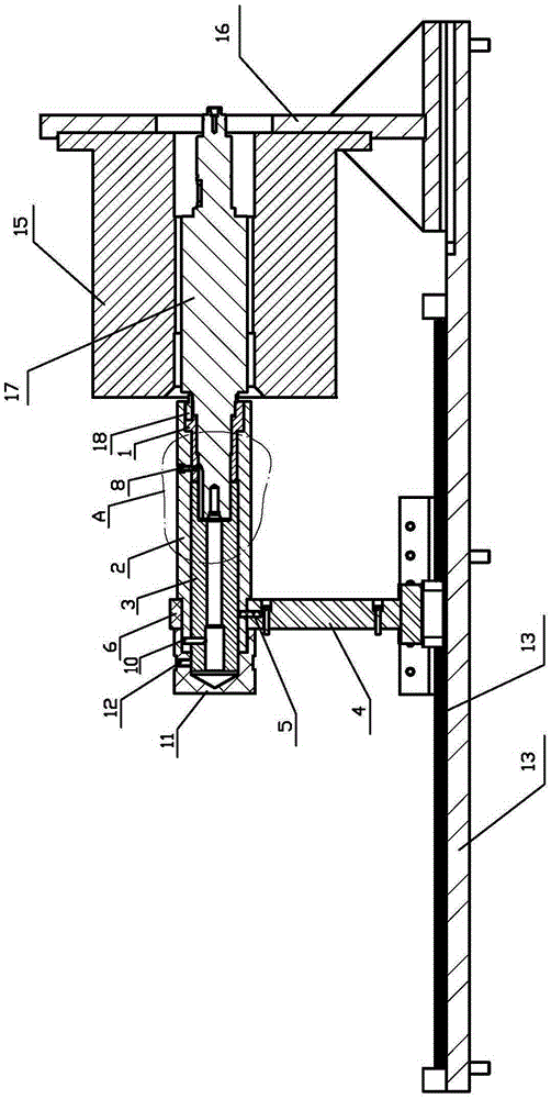
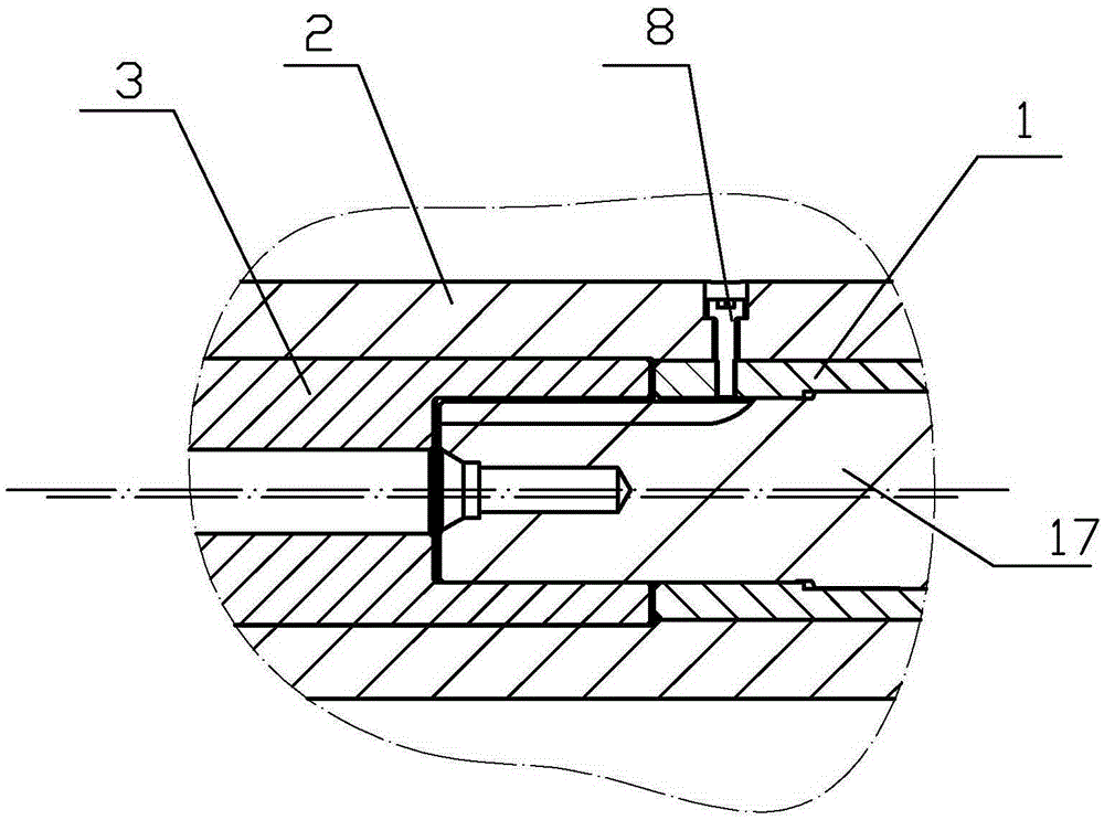
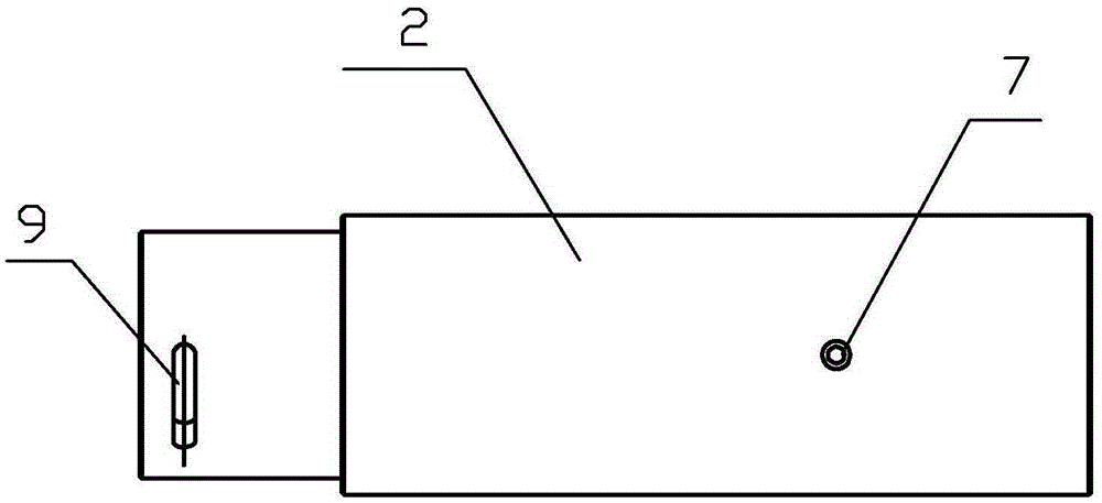
[0025] Embodiment: The rotor shaft end locking device of this embodiment, such as figure 1 As shown, it includes support base 4, positioning sleeve 1, fixed sleeve 2 and locking sleeve 3, the front end of fixed sleeve 2 is fixed on a support base 4, and there is a vertical upward positioning pin on the support base 4 5. The positioning pin 5 is inserted into the front part of the fixed bushing 2, and the fixed gland 6 is installed on the opposite side of the front part of the fixed bushing 2 and the positioning pin 5. The locking bushing 3 and the positioning bushing 1 are installed in the shaft hole of the fixed bushing 2, the locking bushing 3 is in front, the positioning bushing 1 is behind, and the front end of the locking bushing 3 protrudes from the fixed bushing The front end of 2, the rear end of the axle hole of locking axle sleeve 3 is a shoulder hole, and the shoulder hole and positioning axle sleeve 1 are close to each other. Such as figure 2 As shown, there is ...


PUM


Abstract

The invention relates to a rotor shaft end locking device and method. The rotor shaft end locking device comprises a positioning shaft sleeve, a fixing shaft sleeve and a locking shaft sleeve, wherein the front end of the fixing shaft sleeve is fixed on a supporting seat; the locking shaft sleeve and the positioning shaft sleeve are arranged in the fixing shaft sleeve in a sleeving manner; the locking shaft sleeve is arranged at the front part, the positioning shaft sleeve is arranged at the rear part, and the front end of the locking shaft sleeve extends from the front end of the fixing shaft sleeve; a shaft hole of the fixing shaft sleeve is an eccentric hole, a shaft hole of the locking shaft sleeve is also an eccentric hole, and the eccentric distance of the shaft hole of the fixing shaft sleeve is the same as that of the shaft hole of the locking shaft sleeve, and eccentric directions are opposite. The locking method comprises the following steps of fixing the front end of the fixing shaft sleeve to the supporting seat; sequentially mounting the locking shaft sleeve and the positioning shaft sleeve in the shaft hole of the fixing shaft sleeve in a sleeving manner; enabling the front end of the rotor shaft allowed to be magnetized to extent into the shaft hole of the locking shaft sleeve and the shaft hole of the positioning shaft sleeve; and rotating the locking shaft sleeve so that the rotor shaft is locked and is no longer flexible. According to the rotor shaft end locking device disclosed by the invention, damage to the surface of the rotor shaft is avoided, and the rotor shaft end locking device is convenient to disassemble and assembly, and firm to lock, and the efficiency is improved.

Description

technical field [0001] The invention relates to a rotor shaft clamping device, in particular to a rotor shaft end locking device and a locking method thereof which can protect the surface quality of the rotor shaft and facilitate repeated disassembly and assembly. Background technique [0002] The production of the motor rotor shaft needs to go through various processes such as magnetization, and the rotor shaft needs to be clamped repeatedly. As for the servo motor, due to its very strict requirements on the servo performance and control accuracy, it is required that the surface of the rotor shaft of the motor can still guarantee the due quality to the greatest extent after the production of various processes, and reduce the damage to the surface of the rotor shaft . However, the current clamping equipment, on the one hand, is inconvenient to disassemble and assemble, time-consuming and laborious, on the other hand, it will still cause damage to the surface of the rotor sh...

Claims


Application Information

Patent Timeline
Patent Type & Authority Applications(China)
IPC IPC(8): B25B11/00
CPCB25B11/00
Inventor 齐玙珂江思敏李星星叶鹏金国华林海
Owner 安吉桢正运动控制技术有限公司
Why Eureka
Try Eureka