Projection display method and system

A technology for projecting and projecting images, applied in the field of projection display methods and systems, can solve the problems of high cost, complicated control of splicing display images, etc., and achieve the effect of easy control

Inactive Publication Date: 2016-04-27
HISENSE VISUAL TECH CO LTD
View PDF5 Cites 12 Cited by
  • Summary
  • Abstract
  • Description
  • Claims
  • Application Information

AI Technical Summary

Problems solved by technology

[0006] The embodiment of the present invention provides a projection display method and system, which can realize splicing display of projected images throu

Method used


Image

  • Projection display method and system
  • Projection display method and system
  • Projection display method and system

Examples


Embodiment 1

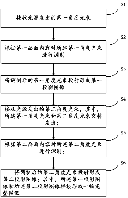
[0035] Such as figure 1 As shown, the embodiment of the present invention provides a projection screen display method,

[0036] Step S1: receiving the first angle light beam emitted by the light source;

[0037] The light source can be a laser light source or an LED light source. It is preferably a laser light source, with high brightness and good color gamut.

[0038] Step S2: Modulating the light beam at the first angle according to the content of the first picture.

[0039] Before step S2, it also includes dividing an image to be displayed into a first picture and a second picture,

[0040] Wherein, the specific division manner of the first picture and the second picture is, for example, left and right division, or up and down division.

[0041] The light beam at the first angle corresponds to provide illumination for the first picture, and according to the content of the first picture, specifically the gray scale RGB component value of each pixel, determine the actuall...

Embodiment 2

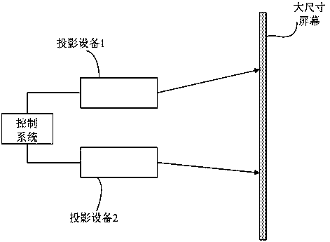
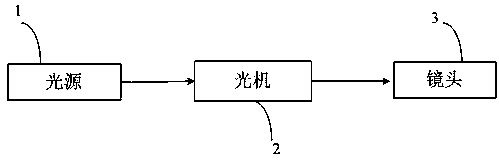
[0056] Embodiment 2 of the present invention provides a projection screen display system, such as image 3 As shown, it includes light source 1, light engine 2, and lens 3. Wherein, the light source 1 is used to alternately emit the first-angle light beam and the second-angle light beam to provide illumination for the light machine 2 . The optical machine 2 is configured to receive the first angle beam and the second angle beam, and modulate the first angle beam and the second angle beam according to the content of the first picture and the second picture respectively. The lens 3 is used to respectively project the modulated first-angle light beam and second-angle light beam to the projection screen to form a first projection image and a second projection image, wherein the first projection image and the second projection image are spliced ​​to form a full image.

[0057] The imaging principles of the following projection display systems provided by the embodiments of the pr...


PUM


Abstract

The invention discloses a projection display method and a projection display system. The projection display method comprises the steps that: a first angle light beam and a second angle light beam are output through alternating light sources, so that the light beams of different light sources illuminate different display images, and are modulated corresponding to content of the different display images; and the modulated light beams at different angles form images to be output in sequence, and a first projection image and a second projection image are formed. According to the projection display method and the projection display system, a complete image is formed by the first projection image and the second projection image by utilizing the persistence effect of human vision, thus a large-size image can be displayed by utilizing one set of projection display equipment, the control is simple, and the cost is low.

Description

technical field [0001] The present invention relates to the technical field of projection display, in particular to a projection display method and system. Background technique [0002] A projection display device usually includes a light source, an optical machine and a lens, wherein the light source provides illumination for the optical machine. Traditional light sources include mercury lamps, LED light sources, and the emerging laser light source. [0003] The core component of the optical machine is a digital micromirror device (Digital Micromirrored Device, DMD), which is a fully digital spatial light modulator, which uses fast switching speed and pulse width modulation to produce precise image color and grayscale control. The surface of the DMD is covered with a two-dimensional micromirror array. Each microlens is equivalent to a pixel in the projection screen. Each microlens can be deflected freely. Different deflection angles of the microlens will present different s...

Claims


Application Information

Patent Timeline
IPC IPC(8): G03B21/20H04N9/31
CPCG03B21/2066G03B21/2033H04N9/31
Inventor 徐爱臣赵树斌
Owner HISENSE VISUAL TECH CO LTD
Why Eureka
Try Eureka