
Upper engine base mechanism suitable for device with automatically-demoulded motor coil

An automatic demoulding and coil technology, which is applied in the direction of electromechanical devices, electric components, and manufacturing of motor generators, can solve the problems of high processing cost, low production efficiency, and difficulty in guaranteeing product quality, and achieves a high degree of automation, simple structure, The effect of improving production efficiency

Inactive Publication Date: 2016-04-27
德清奥士玛数控设备有限公司
View PDF4 Cites 0 Cited by
  • Summary
  • Abstract
  • Description
  • Claims
  • Application Information

AI Technical Summary

Problems solved by technology

[0002] In the production process of the motor coil, it is necessary to first install the mold base for coil winding, then wrap the tape, and finally take out the mold base and coil. The existing motor coil production process is manual work, including manual tape wrapping and manual removal of the mold base. And manually take out the coil, there are problems such as high processing cost, low production efficiency and difficult to guarantee product quality
At present, the main difficulty in the use process lies in the placement of the coil, the coordination of the coil before and after demoulding, etc.

Method used


Image

  • Upper engine base mechanism suitable for device with automatically-demoulded motor coil
  • Upper engine base mechanism suitable for device with automatically-demoulded motor coil
  • Upper engine base mechanism suitable for device with automatically-demoulded motor coil

Examples


Embodiment Construction

[0017] Combine below Figure 1 to Figure 7 Specific description embodiment:

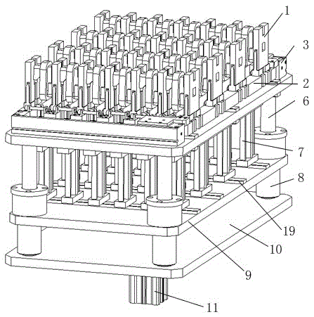
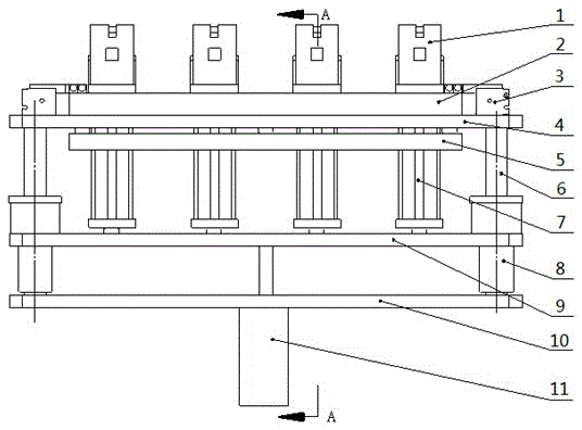
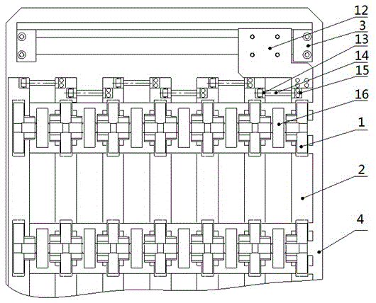
[0018] Such as Figure 1 to Figure 7 As shown, it is suitable for the automatic demoulding device of the motor coil, including the lower machine base plate 10, the upper machine base plate 4, the jacking cylinder 11, the guide post 6, the ejector rod installation plate 9, the ejector rod 7, and the mold frame installation block 2 1. The mold opening and closing cylinder 3 and the mold frame 1, the lower machine base plate 10 and the upper machine base plate 4 are fixed by the guide column 6, the jacking cylinder 11 is arranged below the lower machine base 10 plate, and the output shaft of the jacking cylinder 11 passes through the The lower base plate 10 is connected with the ejector rod mounting plate 9, and the ejector rod mounting plate 9 is pushed to move up and down. The ejector rod mounting plate 9 is slidably arranged on the guide post 6, and the guide post 6 is provided with a guide sleeve 8...


PUM


Abstract

The invention belongs to the technical field of an automatic demoulding tool of a motor coil, and particularly relates to an upper engine base mechanism suitable for a device with an automatically-demoulded motor coil. The upper engine base mechanism suitable for the device with the automatically-demoulded motor coil comprises an upper engine plate, push rods, mould base installation blocks, mould opening and closing cylinders and mould bases, wherein a coil station is formed between two adjacent mould bases; two sides of the upper engine plate are provided with the mould opening and closing cylinders in parallel movement with an installation block sliding rail; and the mould opening and closing cylinders are connected with one mould base installation block through a connection plate. The upper engine base mechanism has the beneficial effects of being simple in structure, reliable, practical and high in automation degree, realizes the automatic demoulding in the production processes of various coils including motors and the like, improves production efficiency and lowers cost.

Description

technical field [0001] The invention belongs to the technical field of automatic demoulding tools for motor coils, and in particular relates to an upper frame mechanism suitable for a device for automatic demoulding of motor coils. Background technique [0002] In the production process of the motor coil, it is necessary to first install the mold frame for coil winding, then wrap the tape, and finally take out the mold frame and coil. The existing motor coil production process is manual work, including manual tape wrapping, manual removal of the mold frame And manually take out the coil, there are problems such as high processing cost, low production efficiency and difficult to guarantee product quality. At present, the main difficulties in the use process lie in the placement of the coil, the coordination before and after the coil is demoulded, and other issues. Contents of the invention [0003] The purpose of the present invention is to solve the above-mentioned techni...

Claims


Application Information

Patent Timeline
IPC IPC(8): H02K15/04
CPCH02K15/04
Inventor 袁京鹏王腾龙
Owner 德清奥士玛数控设备有限公司
Learn More