
Demolding device for injection mold

A demolding device and injection mold technology, applied in the field of injection molding and demolding, can solve the problems of high labor cost, low efficiency, inconvenience, etc.

Inactive Publication Date: 2018-05-18
郑州星联新创信息科技有限公司
View PDF0 Cites 4 Cited by
  • Summary
  • Abstract
  • Description
  • Claims
  • Application Information

AI Technical Summary

Problems solved by technology

Injection molds are divided into thermosetting plastic molds and thermoplastic plastic molds according to the molding characteristics; according to the molding process, they are divided into transfer molds, blow molds, casting molds, thermoforming molds, hot compression molds (compression molds), injection molds, etc. Among them, the hot pressing mold can be divided into three types: overflow type, semi-overflow type and non-overflow type according to the overflow method, and the injection mold can be divided into two types: cold runner mold and hot runner mold according to the loading and unloading method. It can be divided into two types: mobile type and fixed type. At present, demoulding needs to be carried out during the processing of injection molds. However, the existing demoulding device has a simple structure and needs to be carried out manually. The labor cost is high and the efficiency is low, which is very inconvenient. Convenience, for this reason, we propose an injection mold release device to solve the above problems

Method used


Image

  • Demolding device for injection mold
  • Demolding device for injection mold
  • Demolding device for injection mold

Examples


Embodiment Construction

[0016] The following will clearly and completely describe the technical solutions in the embodiments of the present invention with reference to the accompanying drawings in the embodiments of the present invention. Obviously, the described embodiments are only some, not all, embodiments of the present invention.

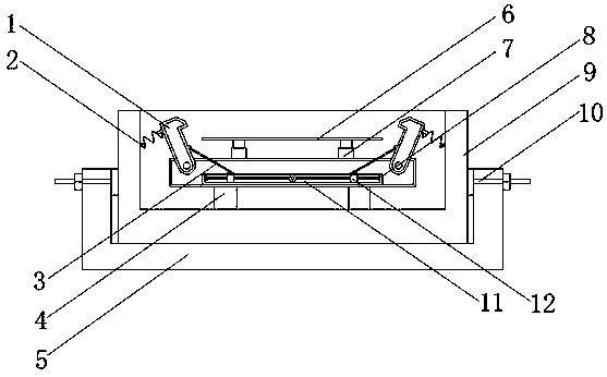
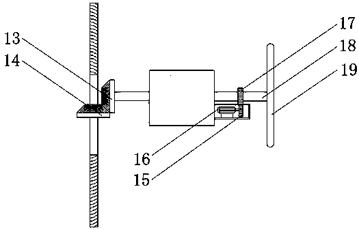
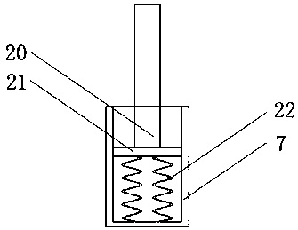
[0017] refer to Figure 1-3 , a demoulding device for an injection mold, comprising a base 5, which acts as a bearing and a support, the upper end of the base 5 is provided with a limiting groove, the bottom of the limiting groove is provided with a carrying box 9, and the carrying box 9 is provided with a placement groove for placing The bottom in the groove is fixed with four supporting blocks 4, the upper ends of the supporting blocks 4 are jointly fixed with a protective box, a cavity is provided in the protective box, a fixed box 8 is provided at the bottom of the cavity, and a chute is provided on the fixed box 8 11. Two sliders 12 are installed in the chute 11...


PUM


Abstract

The invention discloses a demolding device for an injection mold. The demolding device comprises a base. A limiting groove is formed in the upper end of the base. A bearing box is arranged at the bottom inside the limiting groove and provided with a containing groove. Four support blocks are fixed to the bottom inside the containing grove. A protection box is jointly fixed to the upper ends of thesupport blocks and internally provided with a cavity. A fixing box is arranged at the bottom inside the cavity and provided with a sliding groove. Two sliding blocks are mounted in the sliding groove. Threaded rods are rotatably connected to opposite side walls inside the sliding groove correspondingly. A fixing rod is fixed between the two threaded rods. A second conical gear is fixed to the fixing rod. A rotating rod is arranged at one side of the base in a penetrating manner. By means of the injection mold demolding device, automatic demolding of the mold is achieved in the injection molding processing process; processing can be conducted conveniently; efficiency is improved; meanwhile, manual demolding can be conducted according to the circumstance; and the demolding device is convenient to use and suitable for being popularized.

Description

technical field [0001] The invention relates to the technical field of injection molding demoulding, in particular to an injection mold demoulding device. Background technique [0002] Injection mold is a tool for producing plastic products, and it is also a tool for giving plastic products complete structure and precise dimensions. Injection molding is a processing method used in the mass production of certain complex-shaped parts. Specifically, it refers to injecting the heated and melted plastic into the mold cavity under high pressure from the injection molding machine, and after cooling and solidifying, a molded product is obtained. Injection molds are divided into thermosetting plastic molds and thermoplastic plastic molds according to the molding characteristics; according to the molding process, they are divided into transfer molds, blow molds, casting molds, thermoforming molds, hot compression molds (compression molds), injection molds, etc. Among them, the hot p...

Claims


Application Information

Patent Timeline
IPC IPC(8): B29C45/40B29C45/17
CPCB29C45/4005B29C45/1742
Inventor 田振华陈一鸣
Owner 郑州星联新创信息科技有限公司
Learn More