3D printing bearing platform and full-automatic printing method based on bearing platform

A bearing platform, 3D printing technology, applied in the field of 3D printing, can solve problems such as unfavorable automation operation and low efficiency, and achieve the effect of improving efficiency and improving the degree of automation

Active Publication Date: 2019-01-18
SHINING 3D TECH CO LTD
View PDF9 Cites 4 Cited by
  • Summary
  • Abstract
  • Description
  • Claims
  • Application Information

AI Technical Summary

Problems solved by technology

[0003] In 3D printers, the carrying platform is often used as a part of carrying the model. Since the printing material solidifies during the printing process in part of the printing process, and after the printing is completed, the model sticks to the carrying platform, which requires further demoulding. Now There is usually manual demoulding with a knife and shovel, which is not only inefficient, but also not conducive to the automatic operation of production

Method used


Image

  • 3D printing bearing platform and full-automatic printing method based on bearing platform
  • 3D printing bearing platform and full-automatic printing method based on bearing platform
  • 3D printing bearing platform and full-automatic printing method based on bearing platform

Examples


specific Embodiment approach 1

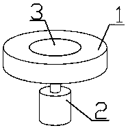
[0030] Such as figure 1 As shown, a 3D printing carrying platform includes a fixed platform 1 and a movable platform 3 spliced ​​with each other, and the bottom of the movable platform 3 is connected with a driving device 2, and the driving device 2 is used to drive the working surface of the movable platform 3 The working surface of the relative fixed platform 1 is raised and lowered. The drive device 2 preferably includes a lift drive mechanism and a push rod for connecting the lift drive mechanism with the movable platform 3 .

[0031] Such as Image 6 with 8 As shown, the movable platform 3 is cylindrical, the fixed platform 1 is provided with a through hole matching the movable platform 3, and the movable platform 3 is arranged in the through hole; the hole wall of the through hole A guide groove 11 is provided on it, and the guide groove 11 preferably extends parallel to the axis of the through hole. At least two connecting columns 31 are evenly distributed in a ring...

specific Embodiment approach 2

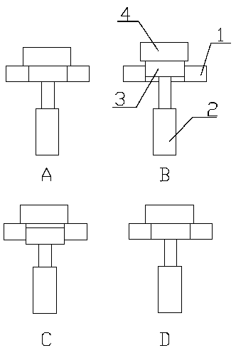
[0034] Such as image 3 with Figure 4 As shown, compared with Embodiment 1, the difference of this embodiment is that the movable platform 3 / fixed platform 1 is provided with a connecting shaft 32, and the movable platform 3 / fixed platform 1 is connected through the connecting shaft. 32 is rotatably connected with the fixed platform 1 / movable platform 3, and the axis of the connecting shaft 32 is parallel to the working surface of the fixed platform 1; the driving device 2 drives the movable platform 3 to rotate around the connecting shaft 32 relative to the fixed platform 1. In order to prevent the drive device 2 from being stuck during the rotation of the movable platform 3, both ends of the drive device 2 are hinged to corresponding components.

[0035] Such as image 3 Shown is a schematic diagram of the demoulding process of the printing platform (in the order of A-B-C-D). When the movable platform 3 rotates relative to the fixed platform 1 , the working surface of th...

specific Embodiment approach 3

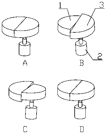
[0036] Compared with Embodiment 1, the difference of this embodiment is that the guide groove 11 is in a spiral shape. Such as Figure 5 to Figure 8 As shown, the guide groove 11 includes several guide units 111, and the number of the guide units 111 is an integral multiple of the number of the connecting columns 31; each guide unit 111 includes two segments 112 with opposite directions of rotation, The two sections 112 are connected into one body, and transition smoothly at the joint; several guide units 111 are connected end to end in turn, and transition smoothly at the joint. The driving device 2 is a motor, and a flexible coupling 5 is arranged between the driving device 2 and the movable platform 3 .

[0037] Since the movable platform 3 moves up and down relative to the fixed platform 1, the model 4 receives a large longitudinal shear force, which may cause damage to the model 4 or cause the model 4 to deform. The spiral guide groove 11 makes the movable platform 3 ro...


PUM


Abstract

The invention relates to the field of 3D printing and specifically discloses a 3D printing bearing platform and a full-automatic printing method based on the bearing platform. The 3D printing bearingplatform comprises a fixed platform and a moveable platform which are spliced with each other; the moveable platform is connected with a driving device used for driving the working surface of the moveable platform to lift or stagger relative to the working surface of the fixed platform; the bearing platform is capable of automatically de-molding through the relative motion of the moveable platformand the fixed platform, so as to increase the degree of automation of printing.

Description

technical field [0001] The invention relates to the field of 3D printing, in particular to a 3D printing carrying platform and a fully automatic printing method based on the carrying platform. Background technique [0002] 3D printing is a kind of rapid prototyping technology. It is a technology based on digital model files and using bondable materials such as powdered metal or plastic to construct objects by layer-by-layer printing. [0003] In 3D printers, the carrying platform is often used as a part of carrying the model. Since the printing material solidifies during the printing process in part of the printing process, and after the printing is completed, the model sticks to the carrying platform, which requires further demoulding. Now There is usually manual demoulding with a knife and shovel, which is not only inefficient, but also not conducive to the automatic operation of production. Contents of the invention [0004] The technical problem to be solved by the pr...

Claims


Application Information

Patent Timeline
Patent Type & Authority Applications(China)
IPC IPC(8): B29C64/245B29C64/379B33Y10/00B33Y30/00B33Y40/00
CPCB29C64/245B29C64/379B33Y10/00B33Y30/00B33Y40/00
Inventor 陈帅姚立伟陈磊王海炳
Owner SHINING 3D TECH CO LTD
Why Eureka
Try Eureka