Variable-displacement swash-plate-type compressor

A variable type, swash plate type technology, applied in the direction of liquid variable volume machinery, mechanical equipment, machine/engine, etc., can solve the problems of pressure leakage, difficult to change the discharge volume, unstable posture of the movable body, etc., to achieve full controllability Effect

Active Publication Date: 2016-04-27
TOYOTA IND CORP
View PDF9 Cites 1 Cited by
  • Summary
  • Abstract
  • Description
  • Claims
  • Application Information

AI Technical Summary

Problems solved by technology

Here, in this compressor, the contact position between the outer peripheral surface of the hinge ball and the swash plate tends to deviate due to manufacturing tolerances, etc., so that the direction of the load acting on the swash plate when the movable body presses the hinge ball prone to change
Therefore, in this compressor, it is difficult for the movable body to press the hinge ball toward the direction of the drive axis, and it is difficult for the movable body to stably reduce the inclination angle of the swash plate.
In addition, in this compressor, since the posture of the movable body is unstable, there is a possibility of pressure leakage in the control pressure chamber.
Therefore, in this compressor, it is difficult to quickly change the discharge capacity according to the operating conditions of the vehicle, etc., thereby making it difficult to exert sufficient controllability.

Method used


Image

  • Variable-displacement swash-plate-type compressor
  • Variable-displacement swash-plate-type compressor
  • Variable-displacement swash-plate-type compressor

Examples


Embodiment 1

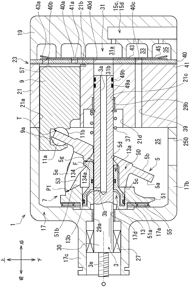
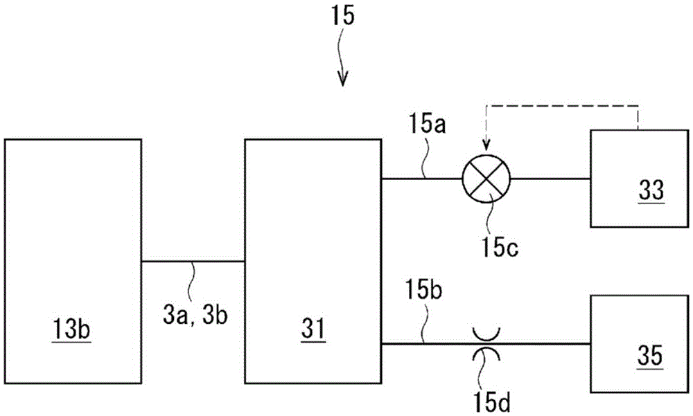
[0059] Such as figure 1 As shown, the compressor of Embodiment 1 has: a housing 1; a drive shaft 3; a swash plate 5; a connecting rod mechanism 7; a plurality of pistons 9; a plurality of pairs of sliding shoes 11a, 11b; figure 2 The control mechanism 15 is shown. Also, for the sake of illustration, in figure 1 In the illustration, the shape of the swash plate 5 is partially simplified. about the latter Figure 7 , Figure 10 Also the same.

[0060] Such as figure 1 As shown, the housing 1 has: a front housing 17 located in front of the compressor; a rear housing 19 located at the rear of the compressor; a cylinder block 21 located between the front housing 17 and the rear housing 19; and a valve unit twenty three.

[0061] The front housing 17 has a front wall 17a extending in the vertical direction of the compressor at the front, and a peripheral wall 17b integrally formed with the front wall 17a and extending from the front of the compressor toward the rear. The fr...

Embodiment 2

[0124] Such as Figure 11 As shown, in the compressor of Embodiment 2, the swash plate 5 has a swash plate main body 50 , swash plate arms 5 e , 5 f , and a contact member 59 . This contact member 59 is also equivalent to the acted part of this invention.

[0125] The contact member 59 is formed separately from the swash plate main body 50 . The contact member 59 is mounted between the swash plate arms 5e, 5f on the front surface 5a of the swash plate main body 50, and is located eccentrically from the drive axis O toward the top dead center corresponding portion T of the swash plate 5.

[0126] A convex portion 59 a protruding forward is formed on the contact member 59 . This convex portion 59a is formed in a substantially hemispherical shape. The convex portion 59a is in point contact with the action surface 134a of the action portion 134 at the action position F. As shown in FIG. Thus, in this compressor, the action portion 134 abuts on the contact member 59 at a positi...


PUM


Abstract

Provided is a variable-displacement swash-plate-type compressor that can be made as compact as possible while being made to exhibit sufficient controllability. This compressor is provided with an actuator (13). The actuator (13) has a movable body (13a) and a control pressure chamber (13b). The actuator (13) has a first movable cylinder part (131), and a working part (134) protrudes in the rear end of the first movable cylinder part (131). A flat working surface (134a) is formed in the working part (134). A convex part (5g) is formed in a swash plate main body (50) in the compressor. The convex part (5g) is positioned on a side of a front surface (5a) of the swash plate main body (50) that faces a top-dead-center corresponding part (T) of a swash plate (5). In this compressor, the working part (134) and the convex part (5g) come in contact at a position eccentric toward the top-dead-center corresponding part (T) from a drive axial center (O).

Description

technical field [0001] The present invention relates to variable capacity inclined plate compressors. Background technique [0002] Patent Document 1 discloses a conventional variable capacity swash plate compressor (hereinafter, referred to as a compressor). The compressor includes a housing, a drive shaft, a swash plate, a link mechanism, a plurality of pistons, a conversion mechanism, and a capacity control mechanism. [0003] A suction chamber, a discharge chamber, a swash plate chamber, and a plurality of cylinder holes are formed in the casing. The drive shaft is rotatably supported by the case. The swash plate can be rotated in the swash plate chamber by the rotation of the drive shaft. The link mechanism is provided between the drive shaft and the swash plate, and allows the change of the inclination angle of the swash plate with respect to the direction perpendicular to the drive shaft center of the drive shaft. The link mechanism has a protruding part and a tra...

Claims


Application Information

Patent Timeline
Patent Type & Authority Applications(China)
IPC IPC(8): F04B27/14
CPCF04B27/1063F04B27/1072F04B27/18F04B27/0878F04B27/1009F04B27/1045F04B49/225
Inventor 山本真也山崎佑介铃木隆容本田和也太田雅树仲井间裕之
Owner TOYOTA IND CORP
Why Eureka
Try Eureka