Vacuum track magnetically levitated train system

A magnetic levitation train and magnetic levitation technology, applied in tunnel systems, sliding/floating railway systems, tracks, etc., can solve the problems of reduced operating efficiency, large air resistance, and non-mechanical emergency braking of the track system, so as to improve the operation The effect of efficiency and broad market prospects

Active Publication Date: 2016-05-04
HUBEI NORMAL UNIV
View PDF10 Cites 22 Cited by
  • Summary
  • Abstract
  • Description
  • Claims
  • Application Information

AI Technical Summary

Problems solved by technology

[0004] The purpose of the present invention is to solve the problem that the current maglev train cannot change lanes, the air resistance suffered during driving is large, the non-mechanical emergency braking cannot be performed when the track system is powered off, and the train needs to stop and wait for passengers to get on and off when the train arrives at the station. To solve the problem of reduced efficiency, a high-speed vacuum track maglev train system is provided for this purpose

Method used


Image

  • Vacuum track magnetically levitated train system
  • Vacuum track magnetically levitated train system
  • Vacuum track magnetically levitated train system

Examples


Embodiment 1

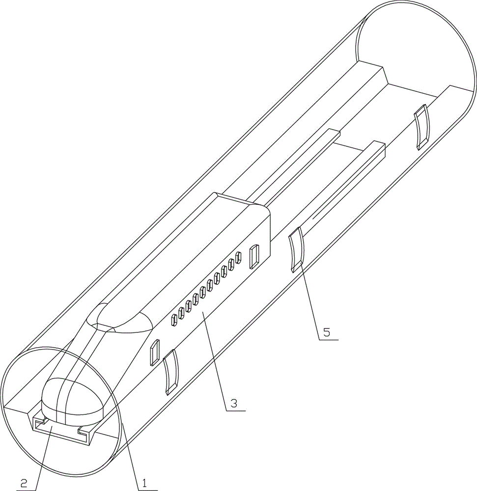
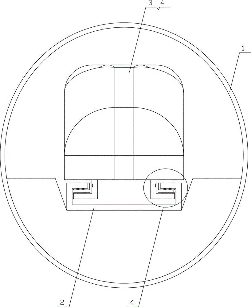
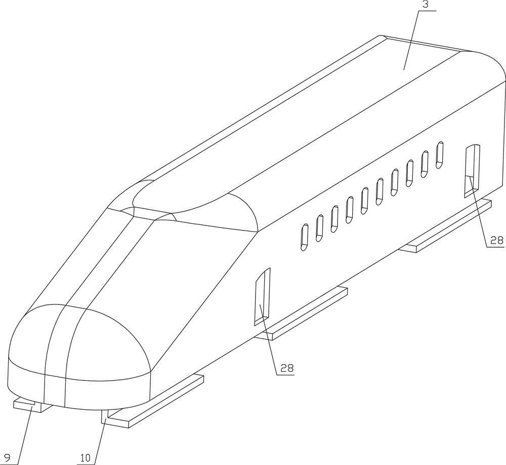
[0033] Example 1, see Figure 1-12 , the present invention includes vacuum tunnel 1, magnetic levitation track 2, magnetic levitation train, station train operation system and driving train operation system and master control train operation system, is provided with several switch doors 5 on vacuum tunnel 1, and maglev train includes locomotive 3 and several compartments 4, several sets of suspension frames are provided on the underside of the headstock 3 and the compartment 4, and an in-vehicle control system and an air circulation system are respectively separately provided in the front end 3 and the compartment 4; the magnetic levitation track 2 and the Each group of suspension frames forms an inwardly cohesive structure, wherein the magnetic levitation track 2 is an integrated inner hook structure, with left and right edges 6, 7 symmetrically arranged toward the inner side of the track, and at the ends of the left and right edges 6, 7 respectively There is an "L"-shaped ma...

Embodiment 2

[0043] Embodiment 2, the present embodiment is based on embodiment 1, in the present embodiment the headstock of the maglev train has the same structure as its respective compartments, and one or more sections for passenger boarding are provided on the maglev track 2 of each site 32 Upper compartment 401, the main train compartment 402 of the moving maglev train, one or more compartments at the end of the main train compartment 402 is the lower compartment 403, wherein the positions of each station 32 are Figure 14 , Figure 15 , Figure 16Respectively represented by a rectangular frame on one side of the maglev track 2; in the station area, three sets of train dispatching systems corresponding to the upper carriage 401, the main train carriage 402 and the lower carriage 403 are respectively arranged to form a station train operation system; There is a section of driving area outside the central station area, and a set of driving train operation systems corresponding to each...


PUM


Abstract

A vacuum track magnetically-levitated train system comprises a vacuum tunnel, a magnetically-levitated track, a magnetically levitated train, a station train operation system, a travelling train operation system and a general control train operation system. A switching door is arranged on the vacuum tunnel. The magnetically levitated train comprises a train head and train compartments. An in-train control system and an air circulation system are arranged inside the train head or the train compartments. A plurality of suspension frames are arranged on the lower side of the train head or the train compartments. The magnetically levitated track and each suspension frame form an inward holding structure. A suspension mechanism, a driving mechanism, a braking mechanism and a guiding mechanism are arranged between the magnetically levitated track and the train head or the train compartments. According to the vacuum track magnetically-levitated train system, the magnetically levitated train can be driven by changing lanes under the vacuum or low-vacuum environment, non-mechanical emergency braking is performed when the track system is powered off, non-contact power supply is performed when the train is operated at high speed, the purpose that the train does not need to be stopped for passengers for getting on or off the train when the magnetically levitated train passes through each station is achieved, the train operation efficiency and the passenger trip comfort are improved, and the market prospect is wide.

Description

technical field [0001] The invention relates to the technical field of maglev trains, in particular to a vacuum track maglev train system. Background technique [0002] The trains running along the railway have a development history of more than two hundred years. With the advancement of science and technology, the speed of trains is getting faster and faster. At present, high-speed rail technology has greatly improved the speed of trains, but after the train's speed reaches a certain range, the resistance of the air and track to the train becomes the biggest obstacle to the continued increase of the train's speed. [0003] In order to solve the above problems, the maglev train system came into being. But existing maglev train system all adopts the mode of open-air driving, does not fundamentally solve the problem of the resistance that air brings to train running. In addition, the design of the track structure of the existing maglev train greatly restricts the operation m...

Claims


Application Information

Patent Timeline
Patent Type & Authority Applications(China)
IPC IPC(8): B61B13/08B61B13/10E01B25/32E01B25/34
CPCB61B13/08B61B13/10E01B25/32E01B25/34
Inventor 刘兴云杨火祥鲁池梅
Owner HUBEI NORMAL UNIV
Why Eureka
Try Eureka