Test equipment calibration device and calibration method thereof

A technology of testing equipment and calibration devices, applied in the direction of instruments, etc., can solve the problems of single function, unfavorable popularization and application, and large investment

Active Publication Date: 2016-05-04
WUCHANG SHIPBUILDING IND
View PDF11 Cites 27 Cited by
  • Summary
  • Abstract
  • Description
  • Claims
  • Application Information

AI Technical Summary

Problems solved by technology

[0007] The present invention provides a test equipment calibration device, and at the same time provides a calibration method for test equipment using the calibration device, which

Method used


Image

  • Test equipment calibration device and calibration method thereof
  • Test equipment calibration device and calibration method thereof
  • Test equipment calibration device and calibration method thereof

Examples


Embodiment 1

[0053] Embodiment 1, the calibration of the large-scale test equipment of the length measurement class (the initial value of 7000mm of the telescoping ruler whose measurement range is 70000mm~12000mm) includes the following steps:

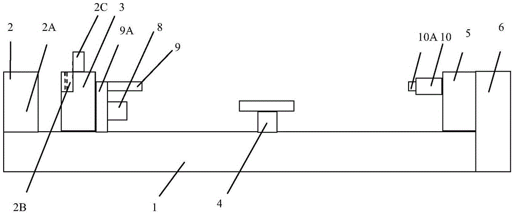
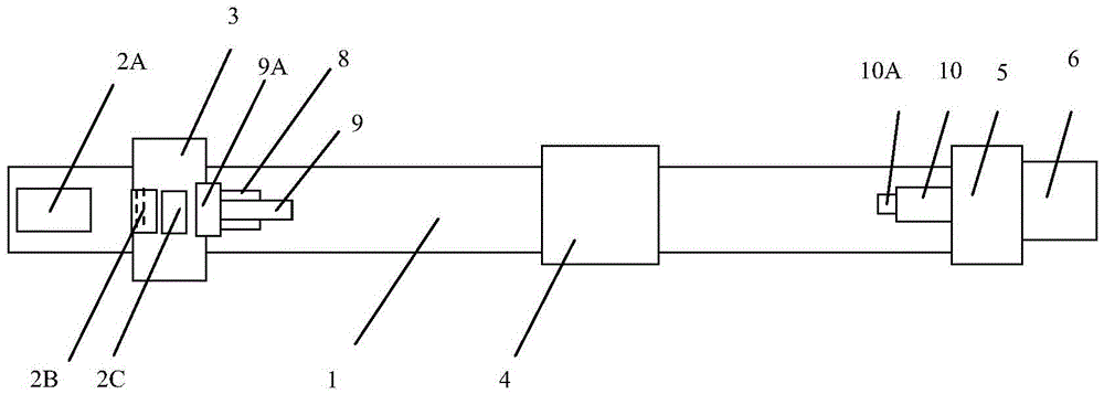
[0054] 1. Adjust the laser head 2A so that its optical axis is parallel to the axis of the guide rail, and the optical axis of the laser head is used as the reference axis, and record the distance H between the axis of the equipment being calibrated and the reference axis 1 =100mm, the axis of the equipment to be calibrated is the axis of the movable measuring head 9 and the measuring head 10A;

[0055] 2. Drive the headstock 3 along the X axis, so that the movable measuring head 9 contacts the measuring head 10A of the fixed measuring rod 10 on the tailstock 5, and the measuring axis of the measuring head 10A is adjusted to the measuring axis of the movable measuring head 9 After being coaxial, it is set to the initial zero position by the process...

Embodiment 2

[0061] Embodiment 2, to the calibration of line pattern class large-scale test equipment (inductive synchronizer ruler 0~5000mm pitch size), comprises the following steps:

[0062] 1. Adjust the laser head 2A so that its optical axis is parallel to the axis of the guide rail, and the optical axis of the laser head is used as the reference axis;

[0063] 2. Drive the head seat 3 to the limit position to the left, place the equipment to be calibrated on the working table of the guide rail 1, adjust the measurement axis of the equipment to be calibrated along the Y direction so that it is coaxial or parallel to the reference axis, and record the measurement of the equipment to be calibrated The distance H between the axis and the reference axis 2 = 400mm, the measuring axis of the equipment to be calibrated is the axis of large-scale testing equipment such as lines;

[0064] 3. Drive the head seat 3 along the X direction and adjust the industrial COMS camera 8 along the Z direct...

Embodiment 3

[0069] Embodiment 3, to the calibration method of large-scale three-dimensional test equipment (laser radar measuring system 0~18000mm measuring range), comprises the following steps:

[0070] 1. Adjust the laser head 2A so that its optical axis is parallel to the axis of the guide rail, and the optical axis of the laser head is used as the reference axis;

[0071] 2. Place the equipment to be calibrated on the left or right end of the guide rail of the calibration device, and adjust the position of the equipment to be calibrated so that its axis is coaxial or parallel to the reference axis; at the same time, fix the target ball or target of the equipment to be calibrated on the head seat 3, make the equipment to be calibrated in working condition and record the projection H of the distance between the axis of the equipment to be calibrated and the reference axis on the XOY plane 3 =100mm, the projection H on the XOZ plane 4 = 100mm;

[0072] 3. According to the working stro...


PUM


Abstract

A test equipment calibration device and a calibration method thereof belong to geometric quantity measurement test equipment, are provided to solve the problem that the existing large-size test equipment calibration device needs large investment, has a single function and is hard to popularize and apply, and are used for geometric large-size equipment comprehensive calibration. The test equipment calibration device of the invention comprises a guide rail, a laser interferometer, a head base, a workbench, a tail base and a processor. According to the calibration method of the invention, through the precision length measurement, 2D angle measurement and 2D auto-collimation functions of the high-precision 5D laser interferometer, the accurate characteristic values of a physical standard (or target) installed on the guide rail in different attitudes in corresponding positions can be obtained. The problem that the technical state and test result accuracy of large special test equipment cannot be controlled effectively is solved, and quick and accurate measurement support is provided for product development and product quality improvement.

Description

technical field [0001] The invention belongs to geometric quantity measuring and testing equipment, in particular to a testing equipment calibration device and a calibration method thereof, which are used for comprehensive calibration of geometric quantity and large-scale equipment. Background technique [0002] The existing standard devices used for calibration of large-scale geometric test equipment all use heavy-duty granite precision baseline guide rail system as the operating platform. Accurate measurement function and the precise measurement function of the engraved line spacing that the line comparator has,) are not conducive to popularization and application; and mature length measuring machines and line line comparators and other equipment have small measurement ranges and single functions, which cannot solve the problems of diverse and complex forms. Calibration and verification of various special test equipment with a large amount and a wide range. [0003] For c...

Claims


Application Information

Patent Timeline
IPC IPC(8): G01D18/00
CPCG01D18/00
Inventor 梅利江郭一鸣陈俊殷义勇冷栋
Owner WUCHANG SHIPBUILDING IND
Why Eureka
Try Eureka