Accelerated corrosion and deterioration testing device for tunnel lining structure in bearing state
An accelerated corrosion test, tunnel technology, applied in the direction of measuring devices, weather resistance/light resistance/corrosion resistance, using a stable bending force to test the strength of materials, etc., can solve the problem that the tunnel lining does not match the real environment and cannot reflect the evolution of performance decline And other issues
- Summary
- Abstract
- Description
- Claims
- Application Information
AI Technical Summary
Problems solved by technology
Method used
Image
Examples
Embodiment 1
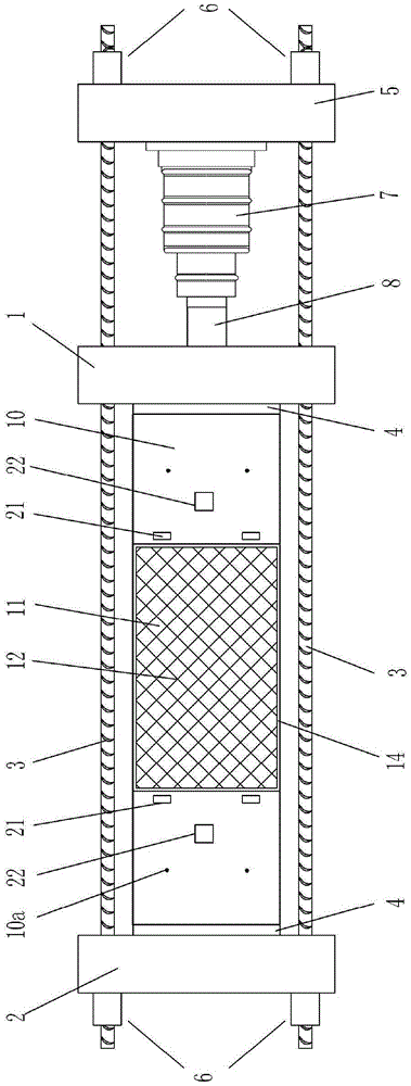
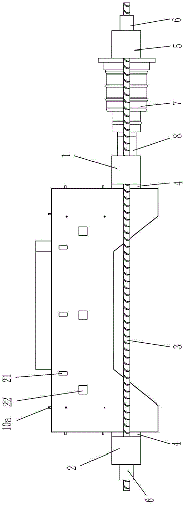
[0031] Figure 1-2 It is shown that a specific embodiment of the present invention is an accelerated corrosion test device for tunnel lining structures under load, which is characterized in that:
[0032] The front and rear sides of the lower part of the tunnel lining member 10 are provided with high-strength force-transmitting threaded tie rods 3, which pass through the left loading beam 2, right loading beam 1 and self-reflexive force beam 5 in turn, and the two ends of the threaded tie rods 3 Anchor bolts 6 are connected, and the left loading beam 2 and the right loading beam 1 are respectively in contact with the left end and the right end of the lower part of the tunnel lining member 10 through the force transmission liner 4; the self-reflexive force beam 5 is located on the right side of the right loading beam 1, and The left side of the self-reflexive force beam 5 is fixed with a horizontal hydraulic jack 7, and the left end of the hydraulic jack 7 is connected to the r...
Embodiment 2
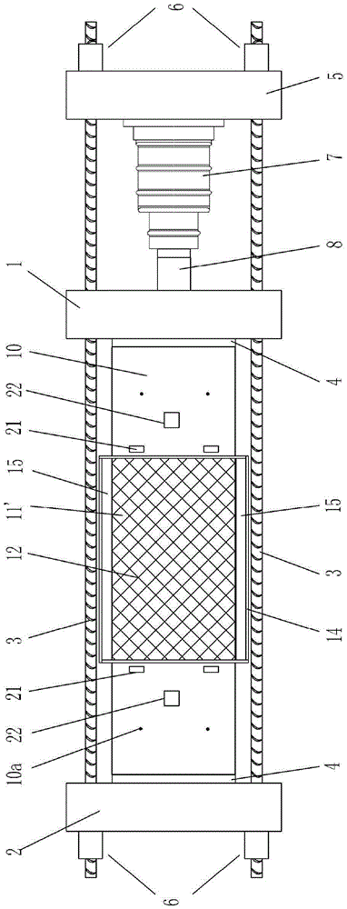
[0038] Figure 3-4 It is shown that the second specific embodiment of the present invention is an accelerated corrosion test device for tunnel lining structures under load, which is characterized in that:
[0039]2. An accelerated corrosion test device for tunnel lining structures under load, characterized in that:
[0040] The front and rear sides of the lower part of the tunnel lining member 10 are provided with high-strength force-transmitting threaded tie rods 3, which pass through the left loading beam 2, right loading beam 1 and self-reflexive force beam 5 in turn, and the two ends of the threaded tie rods 3 Anchor bolts 6 are connected, and the left loading beam 2 and the right loading beam 1 are respectively in contact with the left end and the right end of the lower part of the tunnel lining member 10 through the force transmission liner 4; the self-reflexive force beam 5 is located on the right side of the right loading beam 1, and The left side of the self-reflexiv...
PUM
 Abstract
Description
Claims
Application Information
 - R&D
- Intellectual Property
- Life Sciences
- Materials
- Tech Scout
- Unparalleled Data Quality
- Higher Quality Content
- 60% Fewer Hallucinations
Browse by: Latest US Patents, China's latest patents, Technical Efficacy Thesaurus, Application Domain, Technology Topic, Popular Technical Reports.
© 2025 PatSnap. All rights reserved.Legal|Privacy policy|Modern Slavery Act Transparency Statement|Sitemap|About US| Contact US: help@patsnap.com


