Accelerated Corrosion Deterioration Test Device for Tunnel Lining Structure under Loading Condition

An accelerated corrosion test and tunneling technology, applied in measuring devices, weather resistance/light resistance/corrosion resistance, and testing material strength by applying a stable bending force. And other issues

Active Publication Date: 2019-01-18
SOUTHWEST JIAOTONG UNIV
View PDF2 Cites 0 Cited by
  • Summary
  • Abstract
  • Description
  • Claims
  • Application Information

AI Technical Summary

Problems solved by technology

This test scenario of rusting first and then bearing the load does not match the real environment of the tunnel lining structure under the combined action of load and erosion, and cannot reflect the evolution of performance degradation under the combined action of the water and soil load environment and erosion degradation environment around the tunnel lining structure. law
The reliability of the test results as the basis for tunnel design and maintenance tests needs to be improved

Method used


Image

  • Accelerated Corrosion Deterioration Test Device for Tunnel Lining Structure under Loading Condition
  • Accelerated Corrosion Deterioration Test Device for Tunnel Lining Structure under Loading Condition
  • Accelerated Corrosion Deterioration Test Device for Tunnel Lining Structure under Loading Condition

Examples


Embodiment 1

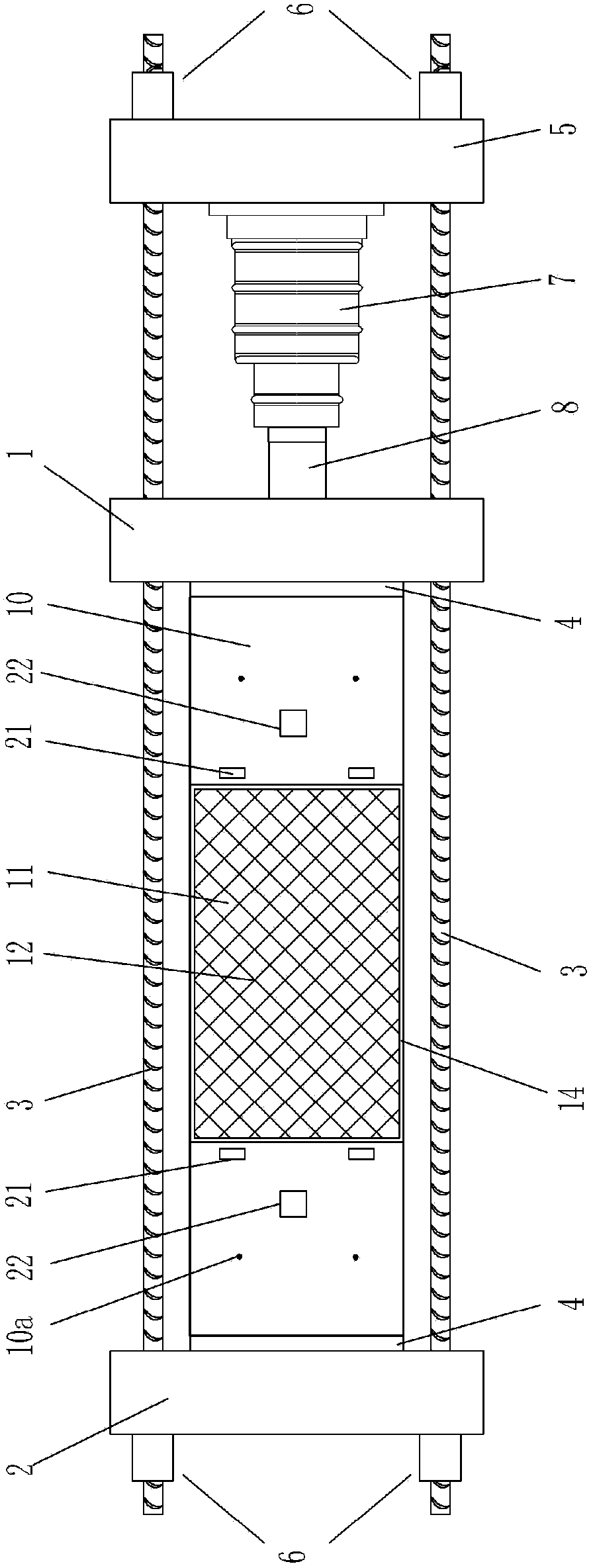
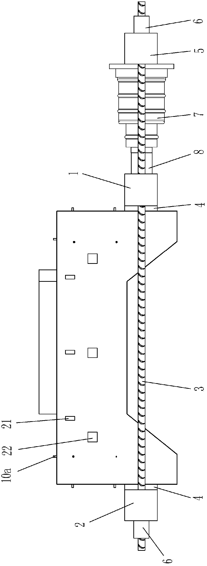
[0031] Figure 1-2 It is shown that a specific embodiment of the present invention is an accelerated corrosion test device for tunnel lining structures under load, which is characterized in that:

[0032] The front and rear sides of the lower part of the tunnel lining member 10 are provided with high-strength force-transmitting threaded tie rods 3, which pass through the left loading beam 2, right loading beam 1 and self-reflexive force beam 5 in turn, and the two ends of the threaded tie rods 3 Anchor bolts 6 are connected, and the left loading beam 2 and the right loading beam 1 are respectively in contact with the left end and the right end of the lower part of the tunnel lining member 10 through the force transmission liner 4; the self-reflexive force beam 5 is located on the right side of the right loading beam 1, and The left side of the self-reflexive force beam 5 is fixed with a horizontal hydraulic jack 7, and the left end of the hydraulic jack 7 is connected to the r...

Embodiment 2

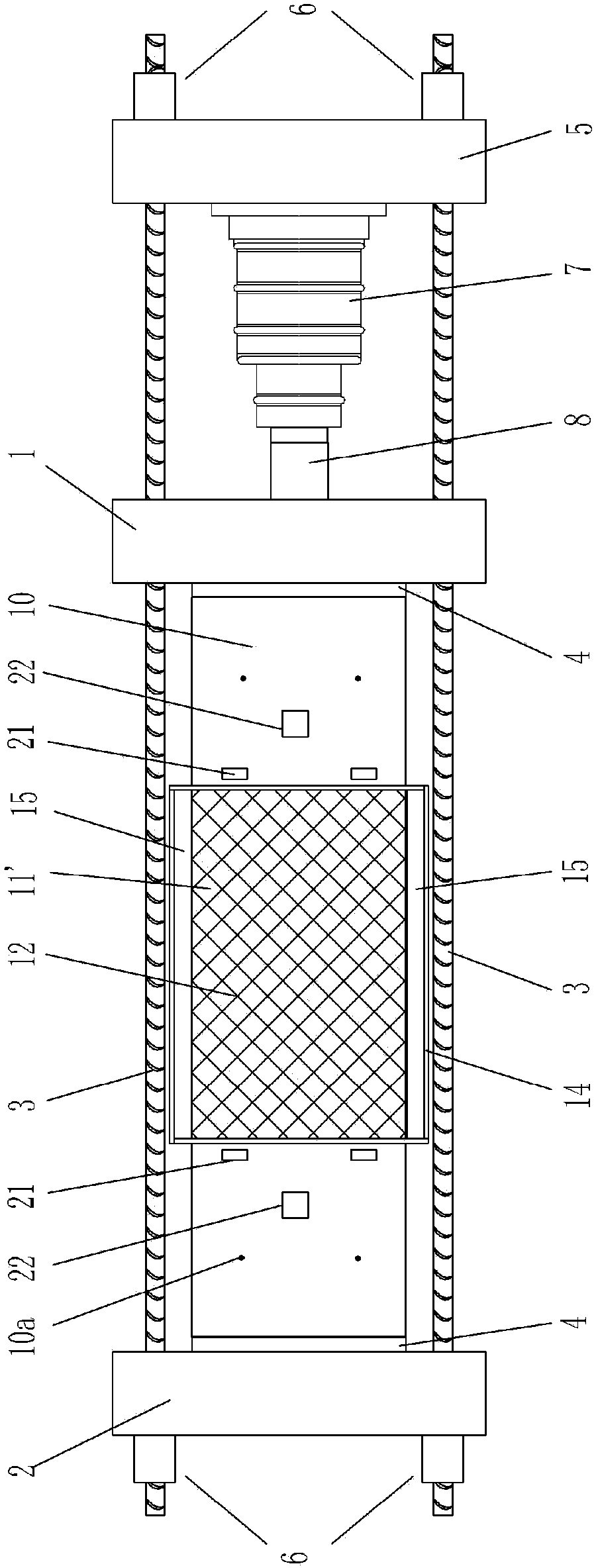
[0038] Figure 3-4 It is shown that the second specific embodiment of the present invention is an accelerated corrosion test device for tunnel lining structures under load, which is characterized in that:

[0039]2. An accelerated corrosion test device for tunnel lining structure under load-bearing state, characterized in that:

[0040] The front and rear sides of the lower part of the tunnel lining member 10 are provided with high-strength force-transmitting threaded tie rods 3, and the high-strength force-transmitting threaded tie rods 3 pass through the left loading beam 2, the right loading beam 1 and the self-reaction beam 5 in turn, and both ends of the threaded tie rod 3 An anchor bolt 6 is connected, and the left loading beam 2 and the right loading beam 1 are in contact with the left and right ends of the lower part of the tunnel lining member 10 respectively through the force transmission pad 4; the self-reaction beam 5 is located on the right side of the right loadi...


PUM


Abstract

An accelerated corrosion test device for tunnel lining structures under load. It is a loading device composed of threaded rods, left and right loading beams, self-reflexive force beams and hydraulic jacks. The loading device is guided by bending moment and axial force. The structural components of the tunnel lining are loaded under control to truly simulate the actual stress state of the tunnel lining structure during the operation period. At the same time, the electrochemical accelerated corrosion system is composed of a steady current DC power supply, the corrosion solution in the top corrosion zone or the omnidirectional corrosion zone, the stainless steel mesh in the corrosion solution, and the steel bars of the tunnel lining structural members. Structural components undergo accelerated corrosion degradation. Strain gauges, displacement gauges, pressure sensors, etc. measure data such as strain and deformation displacement of the tunnel lining structural members in real time, thus realizing the accelerated corrosion degradation test of the tunnel lining structure under load. The test environment is an environment where load and erosion act together, which is closer to the real underground environment of the tunnel lining structure, and can more accurately reflect the evolution law of performance decline of the real tunnel lining structure; thus providing more information for the design and maintenance of tunnel engineering Reliable test basis.

Description

technical field [0001] The invention relates to a test device for accelerated corrosion deterioration of tunnel lining structures under loading conditions. Background technique [0002] With the vigorous development of my country's urban rail transit and cross-river and sea-crossing channel projects at the present stage, traffic tunnel projects have gradually become the main scheme of traffic engineering due to their advantages in traffic security performance and relatively safe structure. [0003] Compared with the ground structure, due to the complexity of the underground water and soil environment, under the joint action of water and soil loads and the surrounding erosion environment, the mechanical properties of the lining structure of the tunnel lining will deteriorate and decline after a period of service: on the one hand, erosion Environmentally specific Cl - , Mg 2+ , SO 4 2- Such corrosive ions will slowly invade the tunnel along with groundwater, seawater, etc....

Claims


Application Information

Patent Timeline
Patent Type & Authority Patents(China)
IPC IPC(8): G01N17/00G01N17/02G01N3/56G01N3/20
CPCG01N3/20G01N3/567G01N17/00G01N17/02G01N2203/0003G01N2203/0023G01N2203/0048G01N2203/024G01N2203/0252G01N2203/0264G01N2203/0676G01N2203/0682
Inventor 何川封坤刘四进安哲立
Owner SOUTHWEST JIAOTONG UNIV
Why Eureka
Try Eureka