Intelligent typhoon resistance traffic safety lamp and control system
A technology for traffic safety and typhoon prevention, which is applied in the field of traffic lights, can solve the problems of disaster weather resistance and not much attention, and achieve the effect of strong wind disaster resistance, reliability assurance and accurate forecasting
- Summary
- Abstract
- Description
- Claims
- Application Information
AI Technical Summary
Problems solved by technology
Method used
Image

Examples
Embodiment Construction
[0027] The accompanying drawings are for illustrative purposes only, and should not be construed as limitations on this patent; in order to better illustrate this embodiment, certain components in the accompanying drawings will be omitted, enlarged or reduced, and do not represent the size of the actual product; for those skilled in the art It is understandable that some well-known structures and descriptions thereof may be omitted in the drawings. The positional relationship described in the drawings is for illustrative purposes only, and should not be construed as a limitation on this patent.
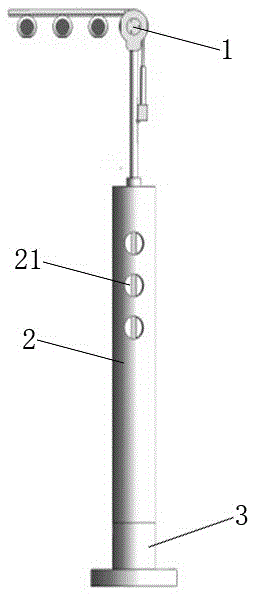
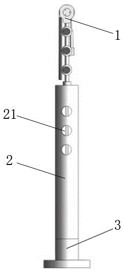
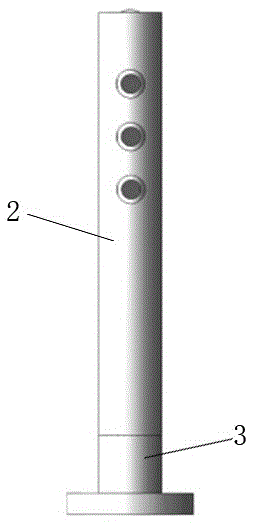
[0028] Such as Figures 1 to 3 As shown, a kind of intelligent anti-typhoon traffic safety lamp, wherein, comprises traffic light head 1, lamp post 2 and lamp base 3, and described lamp post 2 is arranged on the lamp base 3, and described traffic lamp head 1 is arranged on the top of lamp post 2 , the lamp post 2 is a hollow cylinder, the traffic light head 1 can be folded, and has a...
PUM
 Abstract
Description
Claims
Application Information
PatSnap Eureka turns technology decisions into work you can execute. Powered by our Innovation Knowledge Graph, it runs expert workflows across engineering, life sciences, materials and intellectual property. Get your review-ready output in minutes.


