Screw structure and screw driving device

A driving device and screw technology, applied in the direction of screws, connecting members, motor tools, etc., can solve the problems of incongruity and abruptness, affecting the appearance of products, complicated tools, etc., to improve aesthetics, protect aesthetics, versatility and applicability strong effect

A driving device and screw technology, applied in the direction of screws, connecting members, motor tools, etc., can solve the problems of incongruity and abruptness, affecting the appearance of products, complicated tools, etc., to improve aesthetics, protect aesthetics, versatility and applicability strong effect

CN105563402AActive Publication Date: 2016-05-11MARELLI AUTOMOBILE ELECTRONIS GUANGZHOU CO LTD

Image

  • Screw structure and screw driving device
  • Screw structure and screw driving device
  • Screw structure and screw driving device

Examples


Embodiment Construction

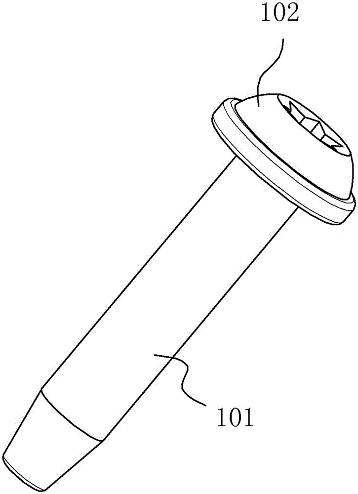
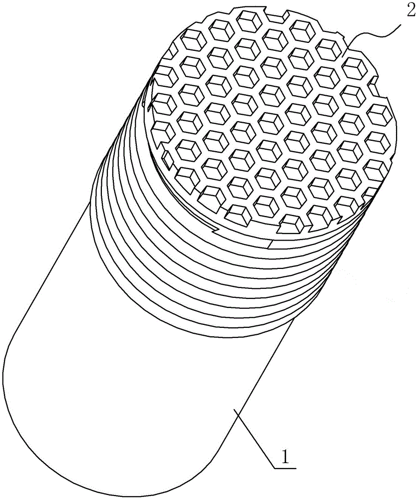
[0021] A screw structure such as figure 2 As shown, it includes a screw body, and the screw body includes a threaded part 1 and a driving part 2, and the driving part is the outer end surface of the screw body.

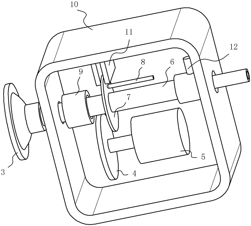
[0022] A screw drive such as Figure 3-5 As shown, it includes a housing 10, a shaft rod 6, the shaft rod 6 runs through the housing, and its front end protrudes from the front side of the housing, and a suction cup 3 matching the driving part of the outer end surface of the screw body is installed at the front end, and the end surface of the suction cup 3 Fitted with the screw driving part, a cavity is provided in the opening of the suction cup, and a vacuum interface connected to the cavity is provided on the back of the suction cup. The shaft 6 is installed on the vacuum interface, and the middle pipe communicates with the cavity of the suction cup. The rear end of the shaft rod 6 protrudes from the rear side of the casing 10 and communicates with the vacuum gene...


PUM


Abstract

The invention discloses a screw structure and a screw driving device. The screw body comprises a threaded part and a driving part. The end face of the outer side of the screw body is the driving part. The screw driving device comprises a sucker, a shaft lever and a driving mechanism driving the shaft lever to rotate. According to the screw structure, the attractiveness of a product can be greatly improved, the surface attractiveness of the screw can be effectively protected through the screw driving device, and universality and applicability of the screw driving device are extremely high.

Description

technical field [0001] The invention relates to a screw structure and a screw driving device for driving the screw. Background technique [0002] A screw is a connecting fastener such as figure 1 As shown, it includes a threaded end 101 at the bottom and a hat-shaped driving head 102 protruding from the top. Depending on the type of screw, the hat-shaped driving head can be provided with different driving grooves such as slots, cross grooves, or inner hexagonal grooves. Usually The outer diameter of the driving head is larger than that of the stud, which is used to compress and fix the profile. When tightening the screws, you need to use a flat-blade screwdriver, Phillips screwdriver, or hexagonal screwdriver corresponding to the drive slot and other driving tools. [0003] When the above-mentioned existing screws are used as fasteners to fix the surface parts of the product, the driving head protrudes from the surface of the product, and its style is inconsistent with the...

Claims


Application Information

Patent Timeline
11 May 2016
Publication
CN105563402A
IPC
B25B21/00; F16B35/00
CPC
B25B21/00; F16B35/00
Inventors
่™ž็ฟ