Clamping unit for molding machine

A technology for molding machines and injection machines, which is applied in the field of mold clamping units for molding machines, and can solve problems such as grease pollution, dullness of mold height adjustment devices, cumbersome replenishment of new grease or additional application, etc.

Inactive Publication Date: 2016-05-11
ENGEL AUSTRIA
View PDF7 Cites 2 Cited by
  • Summary
  • Abstract
  • Description
  • Claims
  • Application Information

AI Technical Summary

Problems solved by technology

This type of kinematic support, although functioning essentially flawlessly, is prone to contamination around the die height adjustment due to outflowing grease
Additionally, the grease "passivates" over time so that the die height adjustment mechanism becomes dull
Refilling or additional application of new grease is indeed cumbersome and is primarily associated with other contamination

Method used


Image

  • Clamping unit for molding machine
  • Clamping unit for molding machine
  • Clamping unit for molding machine

Examples


Embodiment Construction

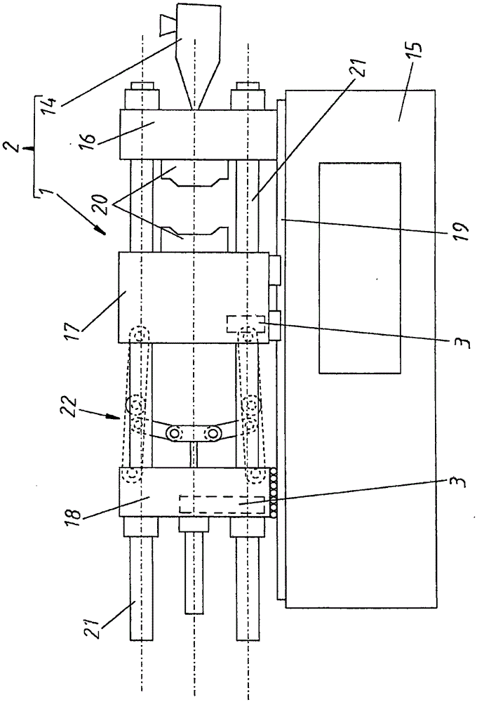
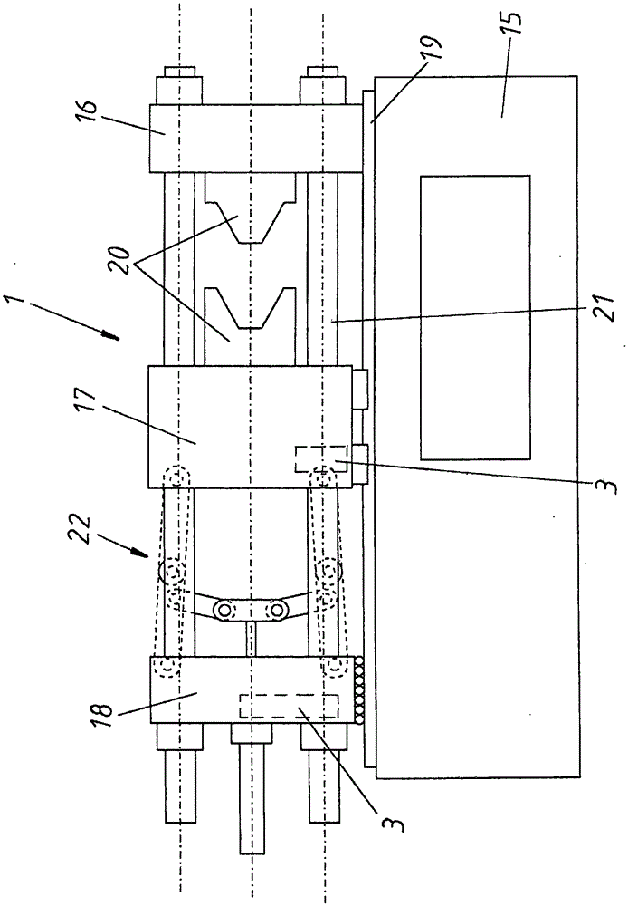
[0025] figure 1 The molding machine 2 is shown schematically in the form of a 3-platen injection machine. However, the molding machine 2 can of course also be a press or an injection molding machine. In particular, the molding machine 2 has an injection unit 14 , shown only schematically, and a clamping unit 1 , shown in detail. A fixed mold clamping plate 16 is fastened to the frame 15 of the clamping unit 1 . The movable mold clamping plate 17 and the end plate 18 are movably supported on the frame 15 via guides 19 . Furthermore, beams 21 are provided along which the relative movement of the movable mold clamping plate 17 and end plate 18 takes place. The relative movement between the end plate 18 and the movable mold clamping plate 17 is effected by a suitable drive, in this case in the form of a toggle mechanism 22 .

[0026] If the other mold halves 20 are now clamped to the mold clamping plates 16 and 17 , an adaptation to the different mold heights which are then gi...


PUM


Abstract

The invention relates to a clamping unit for a molding machine (2), and in particular to a clamping unit (1) for an injection molding machine. The clamping unit is provided with a mould height adjusting apparatus (3), wherein the mould height adjusting apparatus (3) is provided with at least a lubrication area (4) which is at least partially filled with a lubricant (M), in which the lubricant (M) is a lubricating oil. The lubrication area (4) is sealed by a hermetic element (5). The invention also relates to a molding machine, and in particular to an injection molding machine which is provided with an injection unit and the clamping unit in accordance with the invention.

Description

technical field [0001] The invention relates to a clamping unit for a molding machine, in particular an injection machine, which has a mold height adjustment device, wherein the mold height adjustment device has a lubrication area which is at least partially filled with lubricant. The invention also relates to a molding machine with an injection unit and such a clamping unit. Background technique [0002] In most cases the mold height adjustment device is only actuated in the molding machine when a new mold is clamped onto the mold clamping plate of the molding machine. As a result, the mold height adjustment device operates relatively infrequently, contrary to normal close-stroke or quick-stroke mechanisms. In the hitherto known mold height adjustment devices of the clamping unit, the parts moving relative to one another are lubricated with grease. Although this type of kinematic support functions essentially flawlessly, it is prone to contamination around the tool height...

Claims


Application Information

Patent Timeline
Patent Type & Authority Applications(China)
IPC IPC(8): B29C45/17B29C45/66
CPCB29C45/83B29C45/1751B29C45/661B29C2945/76705B29C45/17B29C45/66
Inventor W·卡佩尔米勒S·埃皮希
Owner ENGEL AUSTRIA
Why Eureka
Try Eureka