Zero clearance oil seal assembly

An oil seal and sealing part technology, applied in the direction of engine seals, engine components, mechanical equipment, etc., can solve the problems of reduced turbine efficiency, frictional heat, long contact time, etc., to improve turbine efficiency and prevent static electricity.

Inactive Publication Date: 2016-05-11
曹正奉
View PDF11 Cites 0 Cited by
  • Summary
  • Abstract
  • Description
  • Claims
  • Application Information

AI Technical Summary

Problems solved by technology

[0013] However, in the prior art described above, in the initial start-up or overrun state of the turbine, the rotation of the rotating shaft 10 is unstable and vibration occurs, and at this time, mutual interference occurs between the rotating shaft 10 and the brush seal 60 due to eccentricity. resulting in frictional heat and static electricity
[0014] In the conventional steam turbine as described above, in order to improve the leakage characteristics of the brush seal 60, although it is preferable to shorten the radial gap between the rotating shaft 10 as a rotating body and the brush seal 60 as much as possible, The problem is that the smaller the gap between the rotating shaft 10 and the brush seal 60, the more frequent the mutual interference and the longer the contact time, so the brush seal 60 will wear out early
[0015] In addition, there is a problem that, due to wear of the brush seal 60, thereby increasing the clearance with the rotating shaft 10, and at this time, the leakage amount of steam increases through the developed clearance, so that the efficiency of the turbine decreases, and the oil passes through the increased clearance too much. Leakage and scattering in many places, thus polluting the environment
[0016] As described above, in the improved prior art, due to the vibration of the rotating shaft 10, interference with the brush seal 60 and the seal part 50 still occurs, and thus frictional heat and static electricity are generated at the contact part, and there is a continuation as follows Vicious circle problem: Deformation of the rotating shaft due to heat - early wear - gap expansion due to early wear - foreign matter penetration and fixation due to gap expansion - vibration expansion due to foreign matter fixation - equipment instability and operation stop due to vibration expansion - operation stop Power supply failure and repair delay

Method used


Image

  • Zero clearance oil seal assembly
  • Zero clearance oil seal assembly
  • Zero clearance oil seal assembly

Examples


Embodiment Construction

[0033] Hereinafter, preferred embodiments according to the present invention will be described in detail with reference to the accompanying drawings.

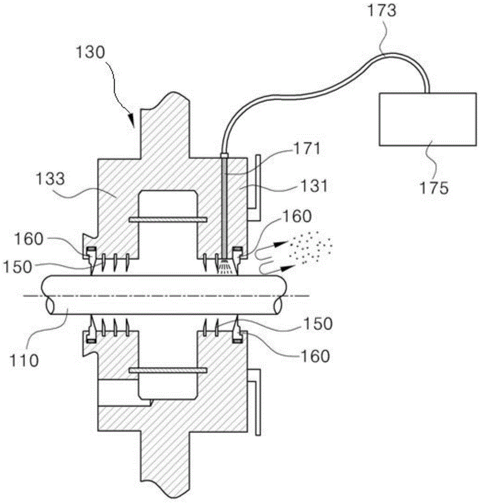
[0034] image 3 is a schematic diagram showing the structure of the oil seal device according to the present invention, Figure 4 It is an enlarged view of important parts illustrating the installation structure of the movable type seal part according to the present invention, Figure 5 It is a sectional view of important parts illustrating the installation structure of the elastic member according to the present invention.

[0035] As shown in the drawings, the present invention relates to an oil seal device that generally includes a ring support 130 , a plurality of seal portions 150 , and a movable seal portion 160 .

[0036] At this time, the ring support body 130 is set to wrap the outer diameter of the rotating shaft 110 . refer to image 3 , the ring support body 130 is formed with a front support part 131 and a rear...


PUM


Abstract

The invention provides a zero clearance oil seal assembly. The zero clearance oil seal assembly comprises an annular supporting body, multiple sealing portions and a movable sealing portion. The annular supporting body is configured to wrap the outer diameter of a rotating shaft and is composed of a front supporting portion and a rear supporting portion. The front supporting portion is provided with a front atmospheric side. The rear supporting portion and the front supporting portion are arranged by a certain distance. The rear supporting portion is provided with a rear bearing side. The sealing portions are arranged on the inner diameter of the front supporting portion and the inner diameter of the rear supporting portion of the annular supporting body respectively, wherein the ends of the sealing portions make contact with the outer diameter of the rotating shaft, so that oil is prevented from leaking to the atmospheric side from the bearing side; the movable sealing portion is arranged on the front outmost side (atmospheric side) of the sealing portions of the front supporting portion and the rear outmost side (bearing) of the sealing portions of the rear supporting portion; and pressure gas is injected from the outer side of the rotating shaft arranged in the rear direction of the movable sealing portion of the front supporting portion, so that an air curtain is formed behind the movable sealing portion, foreign matter is prevented from flowing into the oil seal assembly from the outside, or oil is prevented from being spattered to the outside from the inner side of the oil seal assembly.

Description

technical field [0001] The present invention relates to an oil seal assembly, and in more detail to an oil seal assembly which is respectively provided at a front support part and a rear support part of a ring support body supporting the outer diameter of a turbine rotating shaft. There is a movable sealing part so that even if the shaft of the rotating shaft vibrates in the state of excessive operation at the start of the steam turbine, the movable sealing part can advance and retreat along the vibration direction. Background technique [0002] Generally, an oil sealing device refers to a device performing a sealing function, which is provided outside a bearing housing of a power generation turbine, thereby preventing internal oil from leaking to the outside of the housing. [0003] figure 1 It is a schematic diagram showing the structure of a conventional oil seal device. [0004] The oil seal device as shown in the drawings is composed of: a ring support body 3 provided...

Claims


Application Information

Patent Timeline
Patent Type & Authority Applications(China)
IPC IPC(8): F16J15/16
Inventor 曹正奉
Owner 曹正奉
Why Eureka
Try Eureka