Image display method and image display device

A technology of image display and image, applied in the direction of static indicators, instruments, etc.

Active Publication Date: 2016-05-11
HISENSE VISUAL TECH CO LTD
View PDF7 Cites 7 Cited by
  • Summary
  • Abstract
  • Description
  • Claims
  • Application Information

AI Technical Summary

Problems solved by technology

[0004] Embodiments of the present invention provide an image display method and device, which solves the problem of displaying left and right eye images on odd pixel rows of a liquid crystal panel, and displ

Method used


Image

  • Image display method and image display device
  • Image display method and image display device
  • Image display method and image display device

Examples


Embodiment Construction

[0024] In order to make the object, technical solution and advantages of the present invention clearer, the present invention will be further described in detail below in conjunction with the accompanying drawings. Obviously, the described embodiments are only some embodiments of the present invention, rather than all embodiments . Based on the embodiments of the present invention, all other embodiments obtained by persons of ordinary skill in the art without making creative efforts belong to the protection scope of the present invention.

[0025] Embodiments of the present invention will be described in detail below in conjunction with the accompanying drawings.

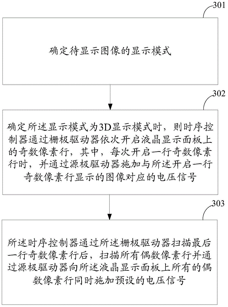
[0026] Such as image 3 As shown, a flow chart of an image display method provided by an embodiment of the present invention, the method includes:

[0027] Step 301: Determine the display mode of the image to be displayed;

[0028] Step 302: When it is determined that the display mode is a 3D display mode, the ti...


PUM


Abstract

The invention discloses an image display method and an image display device. The image display method comprises the steps of determining the display mode of a to-be-displayed image; when a fact that the display mode is a 3D display mode is determined, successively scanning odd-number pixel lines on a liquid crystal display panel by a timing controller through a gate electrode driver, in scanning each odd-number pixel line, applying a voltage signal which corresponds with an image that is displayed on the odd-number pixel line on the scanned odd-number pixel line through the gate electrode driver; and after the timing controller scans a final odd-number pixel line through the gate electrode driver, simultaneously scanning all even-number pixel lines and simultaneously applying a preset voltage signal on all even-number pixel lines on the liquid crystal display panel. According to the image display method provided by the embodiment of the invention, crosstalk is prevented in a 3D manner. The image display method does not affect display of a 3D image and furthermore performs functions of preventing a ghost in display the 3D image and realizing no brightness loss in display a 2D image.

Description

technical field [0001] The present invention relates to the field of display technology, in particular to an image display method and device. Background technique [0002] The current mainstream 3D technology can be divided into shutter 3D (English: Shutter3D) and polarized 3D (English: Polarization3D). Such as figure 1 As shown, in polarized 3D technology, when images are displayed on the display panel, two adjacent pixel rows will have different polarized light. When the viewer wears polarized glasses to watch, between two adjacent pixel rows, only It can be viewed by the left eye, and the other pixel row can only be viewed by the right eye. After processing by the viewer's brain, a 3D image can be synthesized. In this technology, due to the defects of the display panel itself or the defects of polarized glasses, the pixels that should be viewed by the left eye will be seen by the right eye, or the pixels that should be viewed by the right eye will be seen by the left ey...

Claims


Application Information

Patent Timeline
IPC IPC(8): G09G3/36
Inventor 黄顺明
Owner HISENSE VISUAL TECH CO LTD
Why Eureka
Try Eureka