Improved oil-filled cable

A technology of oil-filled cables and oil passages, which is applied in the direction of power cables, insulated cables, cables, etc., can solve the problems of complicated operation, inconvenient installation and use, and inconvenient arrangement, so as to prevent air gaps and oil immersion in a balanced and stable state. Good effect in oil immersion state

Inactive Publication Date: 2016-05-11
盐城市国一电缆材料厂
View PDF4 Cites 2 Cited by
  • Summary
  • Abstract
  • Description
  • Claims
  • Application Information

AI Technical Summary

Problems solved by technology

[0002] The shape of the cable is similar to a rope, and it is usually twisted by several or several groups of wires. Each group of wires is insulated from each other and is often twisted around a center. The entire outer surface is covered with a highly insulating coating; In the air or installed underground or underwater, it is used for telecommunications or power transmission; in order to ensure the normal and stable operation of the cable, the cable is often filled with insulating oil, which can effectively eliminate the air gap in the insulating layer due to load changes. In order to improve the working field strength of the cable; however, the traditional oil-filled cable needs to be equipped with supplementary impregnation equipment at the end, such as a pressure box, a gravity box, etc. This structure is connected with the oil channel of the cable to store and compensate for the volume change of the cable. impregnating agent, and maintain a certain oil pressure; therefore, the operation of traditional oil-filled cables is more complicated during assembly, and there are many factors to be considered, which is inconvenient during installation and use; at the same time, in order to ensure the oil pressure in the cable Stable and uniform, the cable needs to limit a certain height difference when laying, that is, the height difference between the two ends of the cable should not be too large, so as to prevent the cable oil at the high position from being insufficient, so that the air gap will damage the circuit; due to the height difference The restriction of the oil-filled cable is greatly restricted when laying, which causes great inconvenience to the normal power transmission arrangement

Method used


Image

  • Improved oil-filled cable
  • Improved oil-filled cable
  • Improved oil-filled cable

Examples


Embodiment

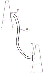
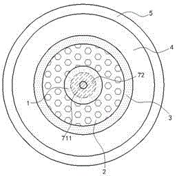
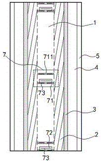
[0015] in Figure 1 to Figure 3 In the illustrated embodiment, the improved oil-filled cable 8 includes an oil passage 1, a conduit 2, a shielding layer 3, an insulating layer 4, and a protective cover 5 from the inside to the outside; the oil passage 1 is filled with insulating oil The conduit 2 is tightly twisted by a metal wire, the metal wire is wrapped by insulating oil-impregnated paper; on both ends of the improved oil-filled cable 8 is also installed with the oil passage 1 Oil storage tank 9; The oil passage 1 is made of hard oil immersion film, and throttle valves 7 are installed equidistantly on the axis of the oil passage 1, such as image 3 Shown in the thin dashed frame; each throttle valve 7 includes two throttle flaps 71 perpendicular to the axis of the oil passage 1, and throttle holes 711 are opened on each throttle flap 71; A throttle plug 72 is movably installed between the throttle plates 71, and the distance between the two throttle plates 71 is smaller tha...


PUM


Abstract

The invention relates to an improved oil-filled cable. The improved oil-filled cable comprises an oil passage, a conductive wire tube, a shielding layer, an insulating layer and a protective sleeve which are arranged from inside to outside. The oil passage is internally filled with insulating oil. The conductive wire tube is formed by metal wires through tight screwing. The two end parts of the oil-filled cable are also provided with oil storage tanks communicated with the oil passage. The oil passage is made from hard oil immersed membranes. Throttle valves are equidistantly installed on the axis of the oil passage. Each throttle valve comprises two throttle sheets perpendicular to the axis of the oil passage. Each throttle sheet is provided with a throttle hole. A throttle plug is flexibly installed between the two throttle sheets. According to the cable, assembling height difference of the oil-filled cable can be expanded, application space of the oil-filled cable can be increased and generation of air gaps in the cable can be effectively prevented.

Description

Technical field [0001] The invention relates to a cable, in particular, an oil-filled cable for power transmission. Background technique [0002] The shape of a cable is similar to a rope, usually by twisting several or several groups of wires, each group of wires are insulated from each other, and often twisted around a center, the entire outer bread has a high-insulation coating; multiple erections In the air or installed underground or underwater, used for telecommunications or power transmission; in order to ensure the normal and stable operation of the cable, the cable is often filled with insulating oil, which can effectively eliminate the air gap in the insulating layer due to load changes. Thereby increasing the working field strength of the cable; but traditional oil-filled cables need to be equipped with supplementary dipping equipment, such as pressure tanks, gravity boxes, etc., at the end. This structure is connected with the oil passage of the cable to store and co...

Claims


Application Information

Patent Timeline
Patent Type & Authority Applications(China)
IPC IPC(8): H01B7/17H01B7/02H01B7/18H01B9/06
Inventor 顾钰锋
Owner 盐城市国一电缆材料厂
Why Eureka
Try Eureka