Sealing mechanism with gas exchange preventing function

A technology of gas exchange and sealing mechanism, which is applied in the direction of engine sealing, mechanical equipment, engine components, etc., which can solve the problems of reduced heat insulation performance of the furnace body, uneven pressure of the briquetting block, large spring expansion and contraction size, etc., achieving multiple times of use, Realize the effect of compaction and reduce the probability of leakage

Active Publication Date: 2016-05-18
苏州正益诚新能源科技有限公司
View PDF9 Cites 4 Cited by
  • Summary
  • Abstract
  • Description
  • Claims
  • Application Information

AI Technical Summary

Problems solved by technology

[0004] (1) The spring of the compression mechanism is inconvenient to assemble and disassemble due to its large expansion and contraction size, and it is prone to fatigue as the number of uses increases, resulting in uneven pressure on the pressing block, which in turn leads to poor sealing performance
[0005] (2) During the use of the second sealing strip, it will be worn, and the gas will easily leak out from the worn port
[0006] (3) The pressing mechanism cannot directly provide space for installing thermal insulation cotton, resulting in a decrease in the thermal insulation performance of the furnace body

Method used


Image

  • Sealing mechanism with gas exchange preventing function
  • Sealing mechanism with gas exchange preventing function
  • Sealing mechanism with gas exchange preventing function

Examples


Embodiment 1

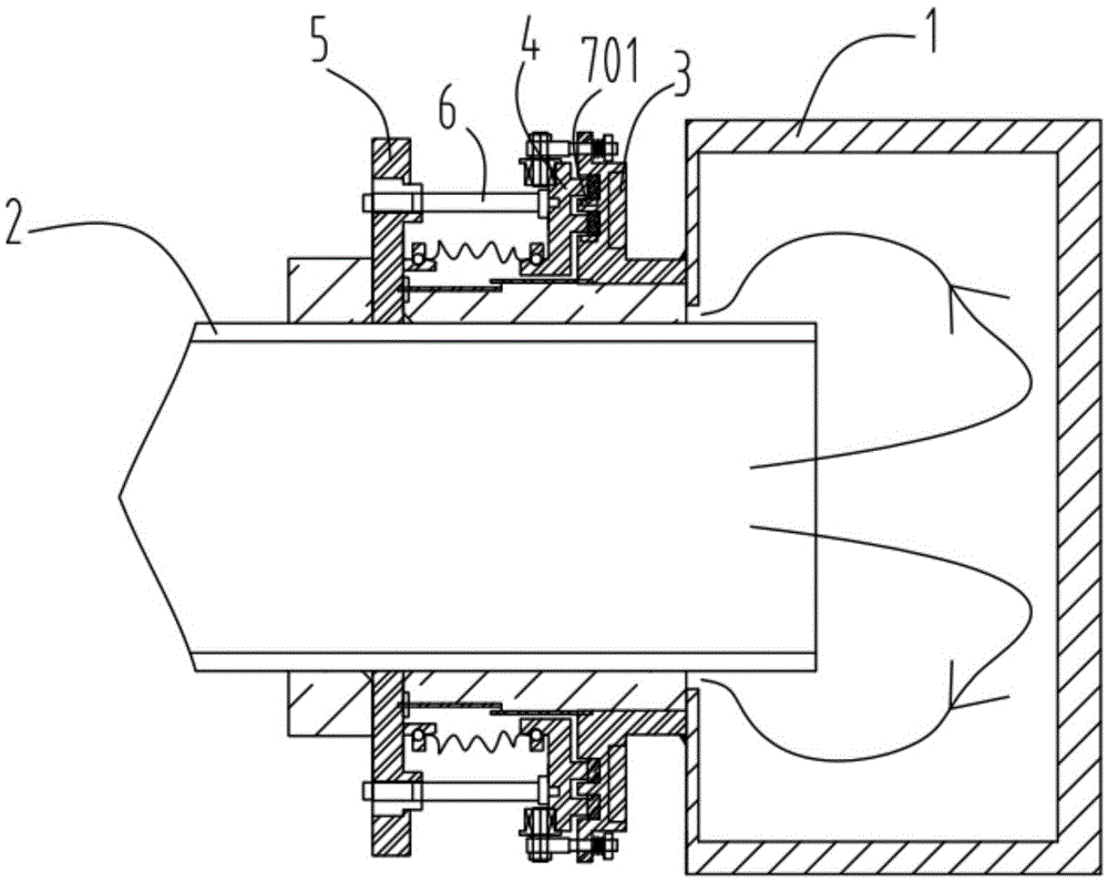
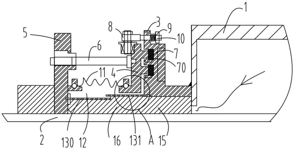
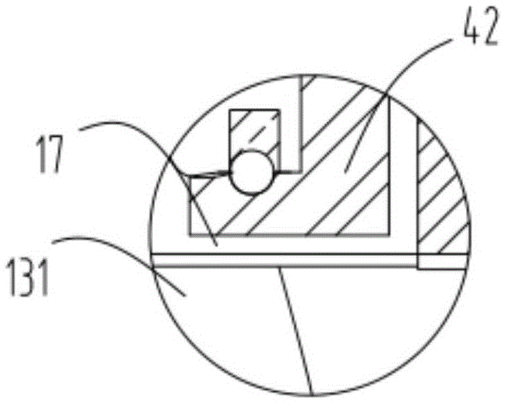
[0038] figure 1 A schematic diagram of the overall structure of Embodiment 1 of the sealing mechanism for preventing gas exchange; figure 2 It is a schematic diagram of part of the structure of the sealing mechanism for preventing gas exchange according to Embodiment 1; Figure 5 It is a schematic diagram of the structure of the guide wheel device defined in the sealing mechanism for preventing gas exchange according to the first embodiment. Such as figure 1 , figure 2 ,and Figure 5As shown, a sealing mechanism for preventing gas exchange includes a fixed part 1, a rotating part 2, a receiving block 3, a pressing block 4, a supporting part 5 and a connecting rod 6, and the rotating part 2 can surround the fixing part 1 Rotate, the receiving block 3 is fixedly arranged on the fixed member 1, the support member 5 is fixedly arranged on the rotating member 1, one end of the connecting rod 6 is fixedly connected with the support member 5, the The other end of the connectin...

Embodiment 2

[0046] Figure 8 It is a structural schematic diagram of the briquetting block in the sealing mechanism for preventing gas exchange according to the second embodiment; Figure 9 It is a schematic structural diagram of the receiving block in the sealing mechanism for preventing gas exchange according to the second embodiment. Such as Figure 8 and Figure 9 As shown, the pressing block 4 has a protruding block 41, and the receiving block 3 is provided with a groove 40 at a corresponding position, and the protruding block 41 is mated with the groove 40 and tightly fitted to form two connections Office 7. It should be noted that, except for this, other structures of this embodiment may be the same as those of Embodiment 1, which need not be repeated here.


PUM


Abstract

The invention relates to sealing mechanism with a gas exchange preventing function. The sealing mechanism comprises a fixing part (1), a rotating part (2), a bearing block (3), a pressing block (4), a supporting part (5) and a connecting rod (6), wherein the supporting part (5) is fixedly arranged on the rotating part (1); one end of the connecting rod (6) is fixedly connected with the supporting part (5); the other end of the connecting rod (6) is fixedly connected with the stress surface (40) of the pressing block (4); the pressing block (4) comprises lug bosses (41); grooves (30) are formed in the positions, corresponding to the lug bosses (41), of the bearing block (3); connecting parts (7) are formed by connecting the lug bosses (41) and the grooves (30) in a close fit manner; and sealing strips (70) are arranged in the connecting parts (7). By adoption of the sealing mechanism, the joint between a main body and the rotating part can be effectively sealed, so as to prevent the situation that gas passes through the gap between the main body and the rotating part for exchange; the pressure of the pressing block is uniform; and the sealing mechanism is simple to adjust, simple in integral structure and high in heat-insulating performance.

Description

technical field [0001] The invention relates to a sealing mechanism for preventing gas exchange, in particular to a sealing mechanism for preventing gas from being exchanged through the gap formed between a fixed part and a rotating body part. Background technique [0002] The invention of the application number 201510072445.5 published on June 24, 2015 discloses a sealing mechanism for preventing gas exchange. The present invention is a sealing mechanism for preventing gas exchange. block, a pressing block that rotates in clearance with the rotating part, and a pressing mechanism that is fixedly connected with the rotating part. The pressing block exerts pressure on the receiving block through the pressing mechanism; the receiving block is provided with a first sealing strip; the cavity of the pressing block Place the second sealing strip; the second sealing strip realizes the sealing of the first gap formed between the pressing block and the outer wall of the rotating part...

Claims


Application Information

Patent Timeline
Patent Type & Authority Applications(China)
IPC IPC(8): F16J15/24F16J15/06C02F11/10
CPCC02F11/10F16J15/06F16J15/24
Inventor 叶玉芳叶华健
Owner 苏州正益诚新能源科技有限公司
Why Eureka
Try Eureka