Concave-convex annular spacing sealing structure with flanges

A sealing structure and flange technology, which is applied in the field of limiting and sealing pipeline structures, can solve the problems of reducing the service life of the pipeline, difficult to ensure the concentricity of the pipeline connection, and increasing the resistance of the pipeline.

Inactive Publication Date: 2012-08-29
江苏吉星管业科技有限公司
View PDF0 Cites 13 Cited by
  • Summary
  • Abstract
  • Description
  • Claims
  • Application Information

AI Technical Summary

Problems solved by technology

Since the pipes are positioned and connected by the flange holes, and the flanges are fixed by bolts, it is difficult to ensure the concentricity of the pipes with the above-mentioned sealing structure; Under the action of the action, the gasket between the sealing surfaces is compressed
The pressure applied on the unit area must reach a certain value to make the gasket deformed and compacted, and the micro-gap formed by machining on the sealing surface is filled to

Method used


Image

  • Concave-convex annular spacing sealing structure with flanges
  • Concave-convex annular spacing sealing structure with flanges
  • Concave-convex annular spacing sealing structure with flanges

Examples


Embodiment 1

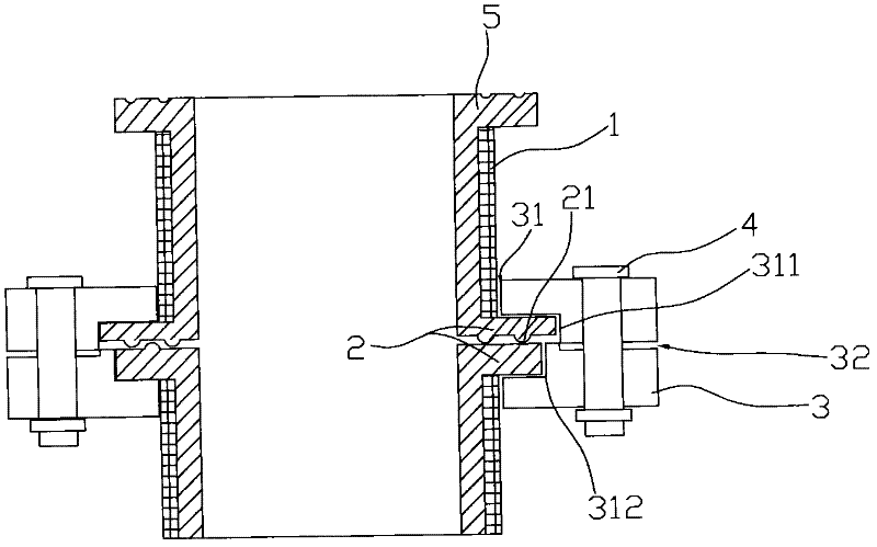
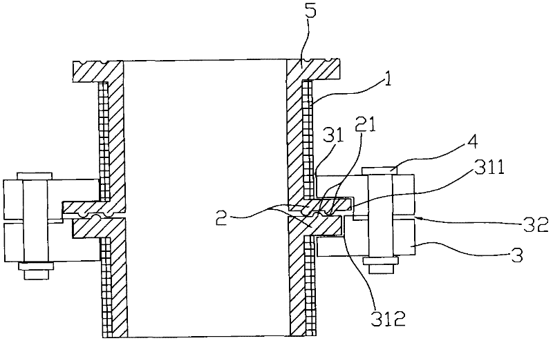
[0020] Embodiment 1: as figure 1 , figure 2 As shown, it consists of two pipe ends 1, two flanges 3 sleeved on the pipe ends 1, a seal 2 and a fastener 4. The flange has an inner end surface 31 and a through hole, and the seal 2 consists of two It is composed of a composite liner 5 set in the inner recesses 311, 312 and sleeved on the inner side of the pipe. The seal 2 can be in close contact after the flange 3 is fastened by fasteners, and the contact surface of the seal 2 can be tightly contacted. One of the surfaces is provided with at least one convex sealing ring 21, in order to improve the sealing performance, the number of convex sealing rings 21 can also be increased to 3 to 5 to achieve a better sealing effect, when When the number of convex sealing rings 21 is increased to 3 to 5, they can also be respectively arranged on two surfaces of the contact surface of the sealing member 2, so that the convex sealing rings 21 are alternated in pairs and facing each other. ...

Embodiment 2

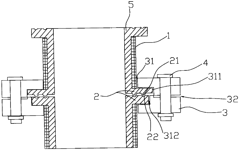
[0021] Embodiment 2: The implementation as described in Example 1: the convex sealing ring 21 on the contact surface of the seal 2 is replaced with a convex sealing ring 21 and a concave sealing ring 22 (such as image 3 ). The convex sealing ring 21 and the concave sealing ring 22 are respectively installed on both sides of the contact surface of the seal, and the convex sealing ring 21 is installed on one surface, and the convex sealing ring 21 is installed on the other surface opposite to it. Matching concave sealing rings 22 , of course, in order to improve the sealing performance, can also be increased to 3 to 5 pairs of convex sealing rings 21 and concave sealing rings 21 that are opposite and match each other.


PUM


Abstract

The invention discloses a concave-convex annular sealing structure with flanges, which comprises two pipe ends, two flanges sleeved on the pipe ends, sealing pieces and fasteners, wherein each flange comprises an inner end surface and a through hole. The sealing structure is characterized in that an inner concave part is arranged on the inner end surface of each flange in a position near the periphery of the through hole; the sealing pieces are two composite linings arranged in the inner concave parts and embedded in the pipe ends, and can be in tight contact with each other after the flanges are fastened through the fasteners; and at least one convex sealing ring is arranged on one of the contact surfaces of the sealing pieces. The sealing structure has the benefit effects that the concentricity of connected pipelines can be guaranteed; the composite linings can not protrude radially due to over extrusion; and the sealing effect can be achieved on the condition that no shear stress is generated.

Description

technical field [0001] The invention relates to a pipeline structure, more specifically to a position-limiting and sealing pipeline structure. Background technique [0002] In petroleum and chemical equipment and pipelines, due to the requirements of the production process, or to facilitate its manufacture, transportation and installation, detachable connection structures are usually used. Common detachable structures include flange connection, thread connection and socket connection, and flange connection has better strength and tightness, and is applicable to a wide range of sizes, and can be applied to equipment and pipelines, so it is the most widely used . [0003] At present, the flange sealing structure of composite pipelines in my country is still commonly used to add sealing gaskets, or to use elastic linings to directly flang to the flange end face to achieve the purpose of sealing. Since the pipes are positioned and linked by the flange holes, and the flanges ar...

Claims


Application Information

Patent Timeline
IPC IPC(8): F16L23/18F16L23/032
Inventor 吉林董凤军王剑秋
Owner 江苏吉星管业科技有限公司
Why Eureka
Try Eureka