Novel proportion electromagnet

A proportional electromagnet and a new type of technology, applied in the field of electromagnets, can solve problems such as the inability to ensure the stability and control accuracy of the electromagnet, the difficulty of ensuring the concentricity of the two bearings, and the increase of the scrap rate of the casing, so as to reduce the scrap rate of the casing. , good concentricity, and the effect of improving overall performance

Active Publication Date: 2014-04-02
NINGBO HOYEA MACHINERY MFG
View PDF4 Cites 15 Cited by
  • Summary
  • Abstract
  • Description
  • Claims
  • Application Information

AI Technical Summary

Problems solved by technology

[0004] The structural design of the above-mentioned proportional electromagnet has the following defects: First, the design is unreasonable. When the electromagnet is processed and clamped, it is necessary to consider the distance between the outer end of the magnetic core tube and the housing (ie figure 1 A1 in the center), between the inner end of the core tube and the shell (ie figure 1 B1 in the center), between the second bearing and the housing (ie figure 1 The matching dimensions of C in middle), there are many matching dimensions between parts, and when clamping, the second bearing needs to be installed in the housing first, and then the magnetic core tube, first bearing, coil assembly, etc. Installed in the shell, the push rod is closely matched with the second bearing, which increases the number of clamping during processing and reduces the overall performance; second, in the actual working process, it is difficult to ensure that the two bearings located at the two ends of the push rod are separated. Concentricity cannot ensure the stability and control accuracy of the electromagnet when it is working, which increases the shell scrap rate of the product, making the shell scrap rate of the product reach more than 10%

Method used


Image

  • Novel proportion electromagnet
  • Novel proportion electromagnet
  • Novel proportion electromagnet

Examples


Embodiment Construction

[0024] The following are specific embodiments of the present invention in conjunction with the accompanying drawings to further describe the technical solutions of the present invention, but the present invention is not limited to these embodiments.

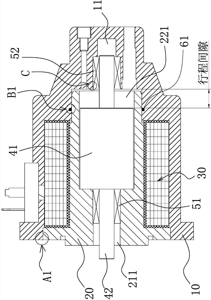
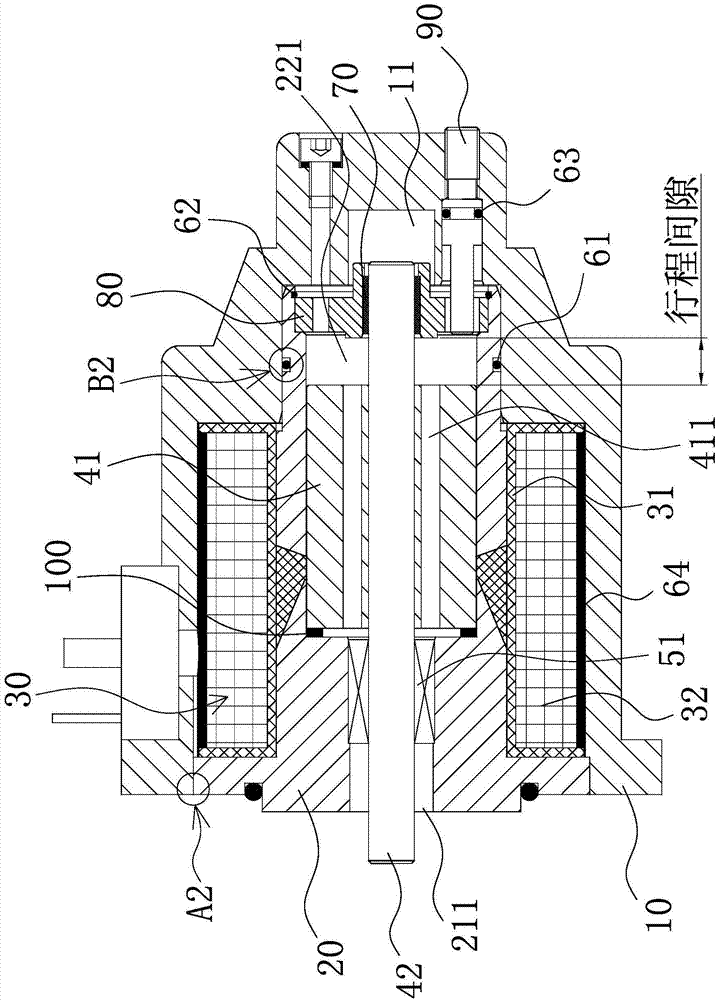
[0025] Such as figure 2 As shown, the proportional electromagnet of the present invention includes a housing 10 having a first cavity and a second cavity 11, and the first cavity is communicated with the second cavity 11, and the magnetic core tube 20 and the surrounding The coil assembly 30 arranged outside the magnetic core tube 20, the housing 10, the magnetic core tube 20 and the coil assembly 30 are hermetically connected. The central part of the magnetic core tube 20 is provided with an output through hole 211 and is connected to the output through hole 211 and the second The accommodating cavity 221 communicating with the inner cavity 11 is installed in the accommodating cavity 221 with an armature assembly composed of an arm...


PUM


Abstract

The invention provides a novel proportion electromagnet and belongs to the technical field of electromagnets. The electromagnet solves the problem that the existing proportion electromagnet is unreasonable in design and cannot ensure concentricity of two bearings arranged at two ends of a push rod. The novel proportion electromagnet comprises a casing with a first inner cavity and a second inner cavity. A magnetic core pipe, a coil assembly and a first sealing ring are arranged in the first inner cavity, an output through hole and a containing cavity are formed in the magnetic core pipe, an armature assembly formed by an armature and a push rod is installed in the containing cavity, a first bearing is sleeved at one end of the push rod, a self-lubricating bearing coaxial with the push rod is sleeved at the other end, a bearing seat for installing the self-lubricating bearing is connected onto one end of the containing cavity close to the second inner cavity in a sealing mode, and the push rod sequentially penetrates the first bearing, the armature and the self-lubricating bearing and partially stretches into the second inner cavity. The proportion electromagnet has the advantages of being reasonable in design, reducing matched size between parts and being capable of ensuring the concentricity of the two bearings arranged at two ends of the push rod.

Description

Technical field [0001] The invention belongs to the technical field of electromagnets, and relates to a novel proportional electromagnet. Background technique [0002] The electromagnet is a kind of magnetic field generated by the energized coil to magnetize the moving iron core and the static iron core that make up the electromagnet, so that the two opposite faces of the moving iron core and the static iron core are opposite magnetic poles, thereby generating a suction force between the moving iron core and the static iron core. Device. The proportional electromagnet is an electromagnet that uses a special magnetic circuit design to make the electromagnetic attraction force not change with the change of the armature displacement, and the electromagnetic attraction force changes in a linear relationship with the current. Proportional electromagnet, as the core component of electro-hydraulic proportional control element to realize the conversion of electrical signal and mechanica...

Claims


Application Information

Patent Timeline
Patent Type & Authority Applications(China)
IPC IPC(8): H01F7/08H01F7/121
Inventor 陈飞飞徐海鹏张策翁之旦
Owner NINGBO HOYEA MACHINERY MFG
Why Eureka
Try Eureka