Pole sheet laser cutting machine

Active Publication Date: 2014-01-16
GEESUN AUTOMATION TECH
View PDF7 Cites 29 Cited by
  • Summary
  • Abstract
  • Description
  • Claims
  • Application Information

AI Technical Summary

Benefits of technology

[0016]The present application has the following beneficial effects: the present application uses laser technologies to achieve the manufacturing process of lithium-ion batteries or super capacitors, makes full use of the excellent characteristics of the laser such as the laser has good monochromaticity and a small divergence angle, and is capable of being focused into a high-power spot at the focal point of the lens, and uses a dedicated laser head and control software as well as a fully automatic manipulator to cut the pole sheet, which could overcome the problems in the prior art that the pole sheet is easily deformed and has larger burrs due to the traditional cutting craft, improves the quality of the manufacturing process, and ensures the product quality of the lithium-ion batteries and

Problems solved by technology

During production of lithium-ion batteries and super capacitors, the manufacturing process of the pole sheet is very critical, and during the current manufacturing of the pole sheet, devices such as die cutting machines, gold die cutting machines, and rotary cutting machines are generally used to achieve pole sheet cutting; however, the pole sheet is made of smaller-thickness aluminum foils and copper foils, which easily wrinkles or deforms the pole sheet during manufacturing of the pole sheet through the cutting devices, thereby resulting in that f

Method used


Image

  • Pole sheet laser cutting machine
  • Pole sheet laser cutting machine
  • Pole sheet laser cutting machine

Examples


Embodiment Construction

[0023]The present application is further described below in detail with reference to specific embodiments and accompanying drawings.

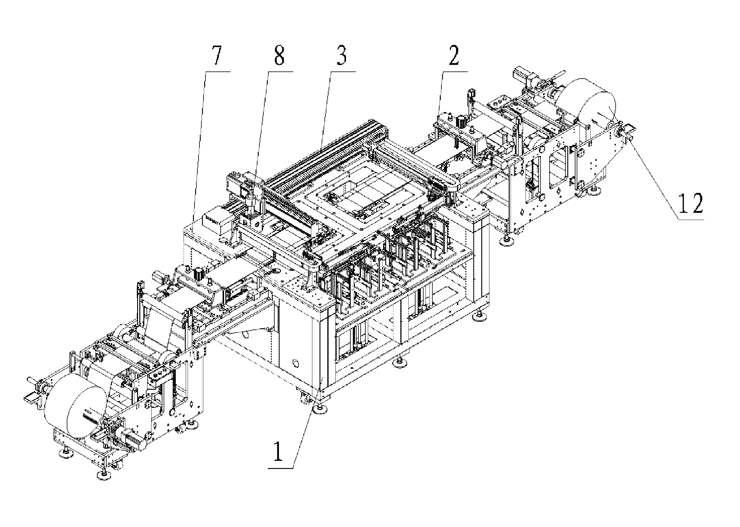
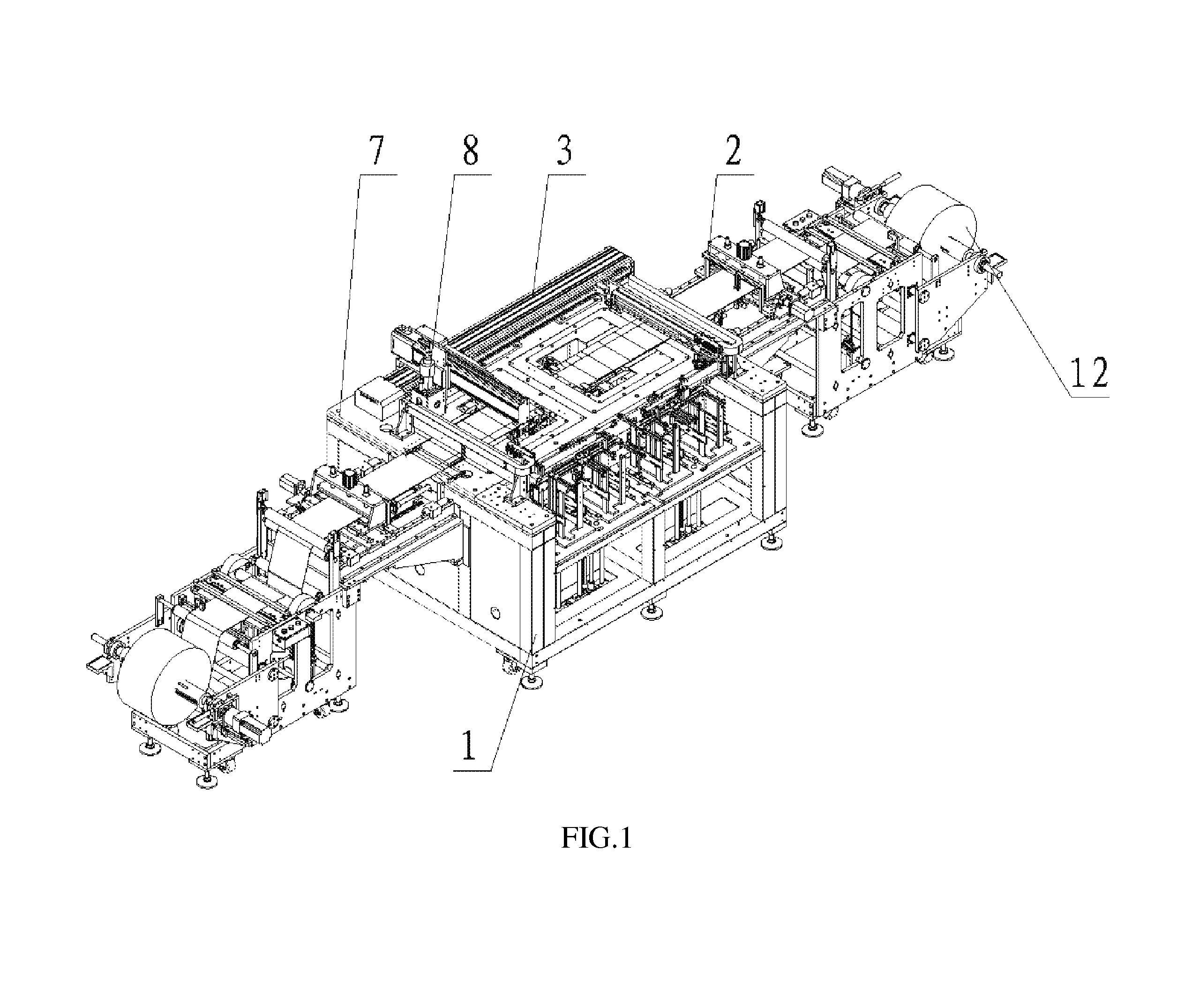
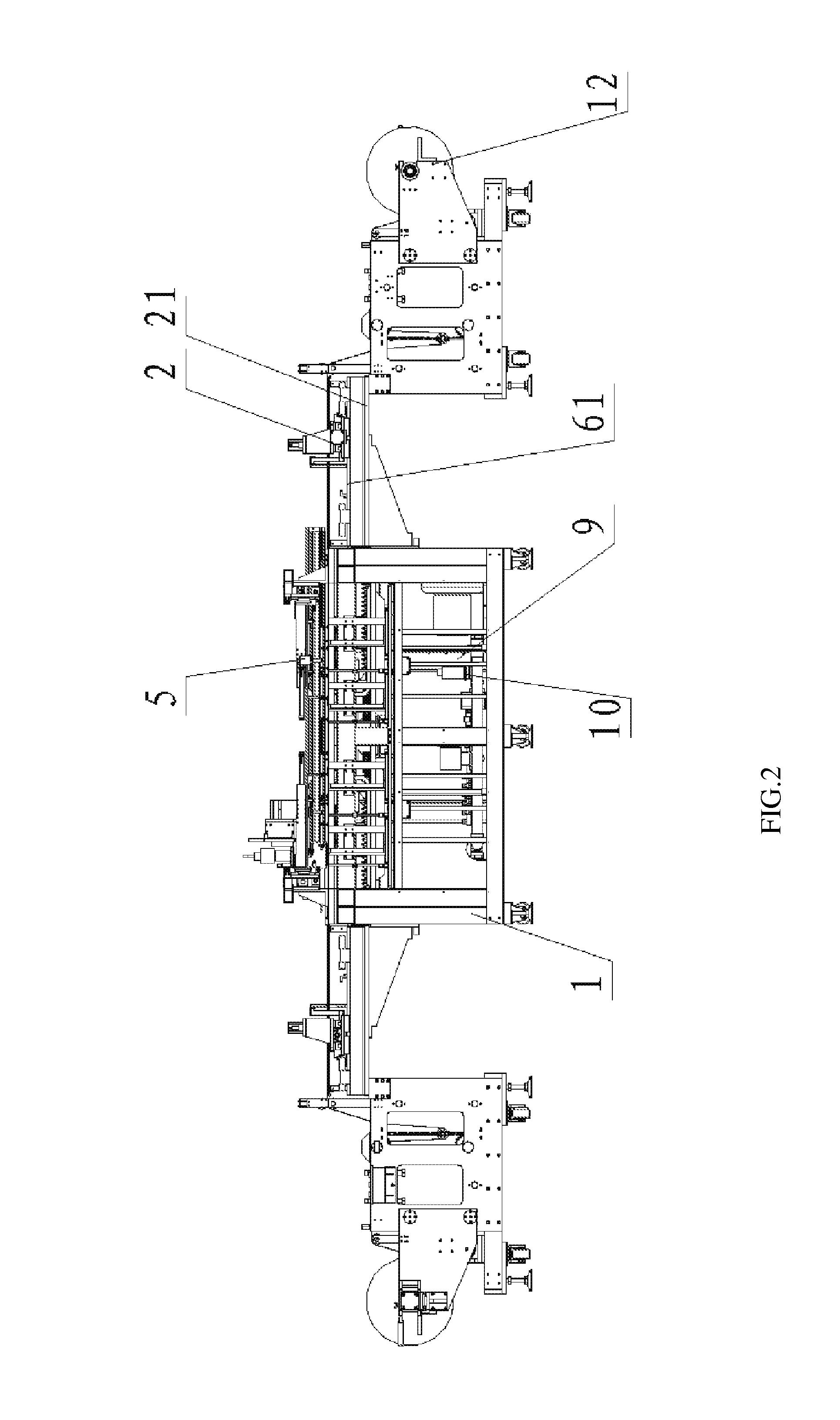
[0024]Referring to FIG. 1 to FIG. 3, the pole sheet laser cutting machine in this embodiment includes a pedestal component 1, a laser cutter 8, a cutting manipulator component 3 for driving the laser cutter 8 to move so as to cut a pole sheet 13, a control system, and at least one sheet feeding assembly. The sheet feeding assembly is used to move the pole sheet 13 to be cut to a cutting platform 7 above the pedestal component 1 so as to be cut into certain sizes and shapes. According to specific requirements, a single-station laser cutter includes one sheet feeding assembly, a double-station laser cutting machine or a multi-station laser cutting machine may include two or more sheet feeding assemblies, and each station may achieve single-width cutting or double-width cutting. The sheet feeding assembly specifically includes a gripping manipulator compon...


PUM

PropertyMeasurementUnit
Pressureaaaaaaaaaa

Abstract

Disclosed is a pole sheet laser cutting machine. It comprises a base frame component, a laser cutting device, a cutting manipulator component for driving the laser cutting device, a control system, and at least one sheet feeding assembly; the sheet feeding assembly comprises a material grabbing manipulator component, a fixed length feeding component and a material releasing component, with both the cutting manipulator component and the material grabbing manipulator component being mounted on the base frame component, the fixed length feeding component being arranged between the material grabbing manipulator component and the material releasing component, and the control system being connected to the cutting manipulator component, the material grabbing manipulator component and the fixed length feeding component. The present invention achieves the sheet making process for lithium ion batteries or super capacitors by applying laser technology, which is able to overcome the problems that existed in the prior art through applying a traditional cutting process so that the pole sheets were easily deformed and the burrs were relatively large, etc., and at the same time, the quality of the sheet making process and hence the rate of acceptable products are improved through the control of the control system.

Description

RELATED APPLICATIONS[0001]This application claims the benefit of PCT application Serial Number PCT / CN2011 / 081514, filed on Oct. 28, 2011, which claimed the benefit of CN application Serial Number 201110040779.6, filed on Feb. 18, 2011, each of which is hereby incorporated herein by reference in the respective entirety of each.FIELD OF THE INVENTION[0002]The present application relates to the field of batteries, and in particular, to a pole sheet laser cutting machine.RELATED ART[0003]During production of lithium-ion batteries and super capacitors, the manufacturing process of the pole sheet is very critical, and during the current manufacturing of the pole sheet, devices such as die cutting machines, gold die cutting machines, and rotary cutting machines are generally used to achieve pole sheet cutting; however, the pole sheet is made of smaller-thickness aluminum foils and copper foils, which easily wrinkles or deforms the pole sheet during manufacturing of the pole sheet through t...

Claims


Application Information

Patent Timeline
IPC IPC(8): B23K26/38
CPCB23K26/38B23K26/0846B23K26/0876B23K26/40B23K37/00B23K37/0235B23K2101/16B23K2101/40B23K2103/50H01M4/04H01M10/049H01M10/052H01M10/0525H01M10/058Y02E60/10Y02P70/50B23K26/08
Inventor CHEN, QIANGXU, GUOGEN
Owner GEESUN AUTOMATION TECH
Why Eureka
Try Eureka