Knife striking and blowing mechanism of direct connected main shaft

A technology of blowing mechanism and main shaft, applied in the directions of metal processing machinery parts, clamping, support, etc., can solve the problems of complex processing technology, high comprehensive cost, high manufacturing difficulty, etc., and achieve simplified processing technology, low comprehensive cost, and airtightness. good effect

Active Publication Date: 2011-01-19
JIANGSU HENGLI MACHINE TOOL
View PDF6 Cites 16 Cited by
  • Summary
  • Abstract
  • Description
  • Claims
  • Application Information

AI Technical Summary

Problems solved by technology

[0005] 1. When cutting, the cutting force of the oil cylinder acts on the main shaft 1 through 41, the connecting rod 15, and the disc spring 27, and then transmits forward to the sleeve 23 and the main shaft box through the front bearing assembly 28 and the end cover assembly 29 30, in this way, the bearing is mainly subjected to backward cutting force when processing the workpiece, and is subjected to forward cutting force when cutting the knife. The bearing is constantly subjected to such a large alternating force, and the accuracy and life will be reduced. It is greatly affected, and in severe cases, it will be damaged
[0006] 2. When blowing the knife is finished, the air passes through the air-tight rotary joint 34 and the air pipe 35 through the transmission shaft in the direct-coupled transmission shaft assembly 36, and then enters the main shaft 1. The structure is complex and difficult to manufacture. The air-tight rotary joint 34 has to withstand a high speed of nearly 10,000 revolutions per minute, poor reliability, high price, and a very long drive shaft needs to make a through hole in the center, the processing technology is relatively complicated, and the overall cost is high
[0007] 3. The compressed air in the blowing air circuit can only be used to blow and clean the taper hole of the main shaft 1 within a short time of cutting, and cannot be used for the ventilation and sealing inside the sleeve 23, so the utilization rate is low

Method used


Image

  • Knife striking and blowing mechanism of direct connected main shaft
  • Knife striking and blowing mechanism of direct connected main shaft
  • Knife striking and blowing mechanism of direct connected main shaft

Examples


Embodiment Construction

[0027] Below in conjunction with accompanying drawing, the present invention is described in further detail:

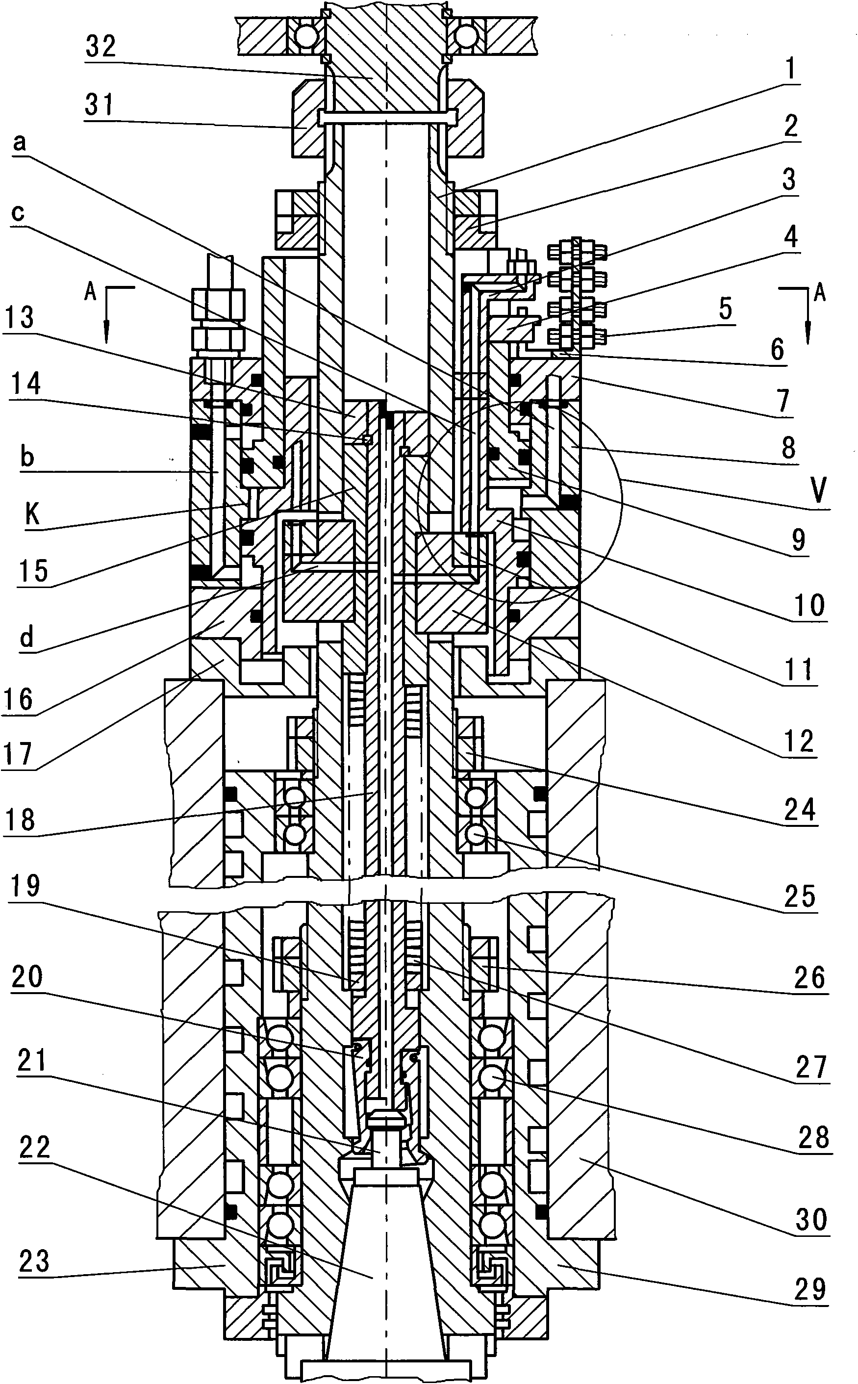
[0028] The present invention mainly comprises main shaft 1, front and rear bearing assembly 28,25, sleeve 23, pull rod 18, connecting rod 15, disc spring 27, pull claw 20 and beating knife oil cylinder. The tail of the main shaft 1 can be connected to a motor or a direct drive shaft assembly 32 through a coupling 31 . This embodiment is for connecting the direct drive shaft assembly. See figure 1 .

[0029] The main shaft 1 is supported in the main shaft housing 30 by the front and rear bearing assemblies 28, 25 and the sleeve 23, the front and rear bearing assemblies 28, 25 are axially fixed by lock nuts 26, 24 respectively, and the end of the main shaft 1 is provided with an end cover 29, The sleeve 23 and the end cover 29 are fixedly connected with the spindle housing 30 . The main shaft 1 can rotate relative to the sleeve 23 and the main shaft housing 30 .

...


PUM


Abstract

The invention relates to a knife striking and blowing mechanism of a direct connected main shaft. The mechanism mainly comprises a main shaft 1, a front bearing assembly 28, a rear bearing assembly 25, a sleeve 23, a pull rod 18, a connecting rod 15, a disc-type spring 27, a drawing jaw 20 and a knife striking oil cylinder, and is characterized in that a piston in the knife striking oil cylinder is formed by assembling an inner piston 10 and an outer piston 9; and acting areas A and B of knife striking oil pressure on the inner piston 10 and the outer piston 9 are equal to each other. The mechanism has the advantages that: the knife striking oil cylinder is an unloading oil cylinder, a bearing does not bear a knife striking force, and the accuracy and the life of the main shaft are ensured; and regular appearance, high sealing property and small size are ensured. An air channel is formed between parts, so that simple structure, high reliability and low cost are ensured, and the direct connected transmission shaft does not need to form a through hole in the centre and has a simple structure. After the knife grabbing is finished, compressed air can be released from the bearing, labyrinth of an end cover and other gaps, so that positive pressure of the air of the interior relative to the exterior is kept, and the main shaft 1 can be cleaned and sealed.

Description

technical field [0001] The invention relates to a component of a gantry machining center of a numerically controlled machine tool, in particular to a direct-connected main shaft knife blowing mechanism. Background technique [0002] The main shaft of the gantry machining center is one of the cores of the entire machine tool. After being equipped with a motor and a transmission device, various processes such as milling, boring, drilling, and tapping can be performed on the workpiece. The accuracy of the main shaft often determines the machining accuracy of the workpiece. There are many ways to drive the main shaft. Among them, the direct-coupled main shaft is directly connected with the motor or the direct-coupled transmission shaft assembly by the coupling 31. There are no intermediate transmission links such as gears and pulleys. The speed is fast, the processing efficiency is high, and the precision is good. . [0003] For the current direct-coupled spindle blowing mechan...

Claims


Application Information

Patent Timeline
Patent Type & Authority Applications(China)
IPC IPC(8): B23Q3/157
Inventor 孙德洲葛东升蔡国保
Owner JIANGSU HENGLI MACHINE TOOL
Why Eureka
Try Eureka