Supercharge Your Innovation With Domain-Expert AI Agents!

A two-axis rotating gluing head

A gluing head and gluing technology, which is applied in the field of gluing heads, can solve problems such as the inability to solve the problem of gluing head rotation, and achieve the effects of improving efficiency, expanding the scope of use, and reducing equipment cost

Active Publication Date: 2018-07-17
DALIAN HUAGONG INNOVATION TECH
View PDF11 Cites 0 Cited by
  • Summary
  • Abstract
  • Description
  • Claims
  • Application Information

AI Technical Summary

Problems solved by technology

[0010] None of the above-mentioned patents can solve the problem of the rotation of the gluing head. At present, there is a lack of a gluing head that can realize two-axis rotation.

Method used


Image

  • A two-axis rotating gluing head
  • A two-axis rotating gluing head
  • A two-axis rotating gluing head

Examples


Embodiment 1

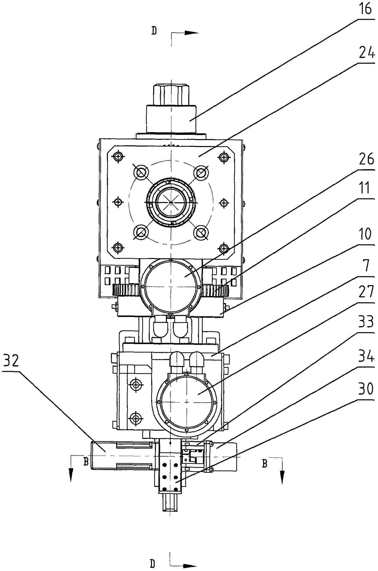
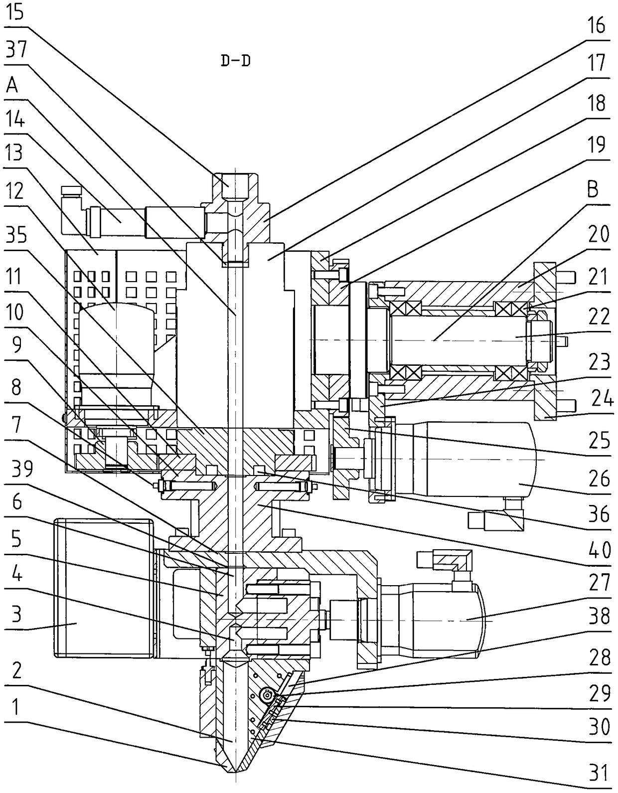
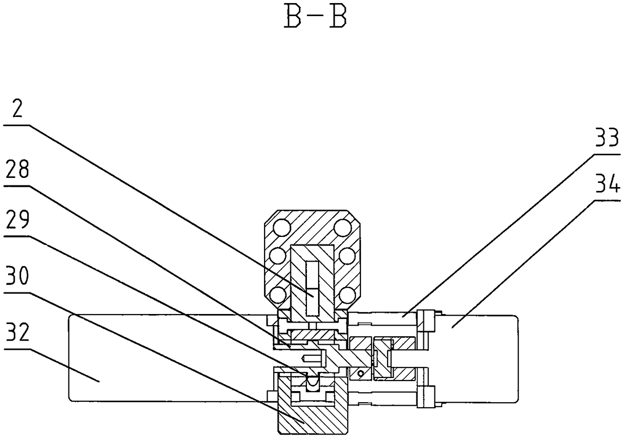
[0031] Embodiment 1: as Figure 1~3 Shown, further illustrate the present invention below in conjunction with accompanying drawing. A two-axis rotating gluing head, used for gluing one-component glue, is characterized in that it includes a gear C19, a gear D25, and a motor B26 that enable the gluing unit 1 to rotate in a vertical plane around the horizontal centerline B , and the gear A9, gear B11, and motor A12 that can make the gluing unit 1 rotate in the horizontal plane around the vertical center line A;

[0032] The connecting plate 24 is fixedly installed on the base of the gluing equipment, the fixed plate B23 and the connecting plate 24 are fixedly connected to the left side and the right side of the bearing seat 20 respectively, and a group of bearings 21 and the rotating shaft 22 are installed in the bearing seat 20, and the rotating shaft 22 The left end passes through the inner hole of the gear C19 and the housing 18 which are fixed together, the housing 18 and th...

Embodiment 2

[0043] Embodiment 2: as Figure 1~3 As shown, what is different from Embodiment 1 is that the gear C19, the gear D25, and the motor B26 do not rotate.

[0044] The motor A12 drives the gear B11 to rotate around the head body 35, and the gluing unit 1 rotates around the vertical centerline A.

Embodiment 3

[0045] Embodiment 3: as Figure 1~3 As shown, what is different from Embodiment 1 is that the gluing unit 1 only includes the gear A9, the gear B11, and the motor A12 that can make the gluing unit 1 rotate in the horizontal plane around the vertical centerline A; The glue unit 1 is a gear C19, a gear D25, a motor B26, a bearing 21, a rotating shaft 22, etc. that rotate in a vertical plane around the horizontal center line B.

[0046] The motor A12 drives the gear B11 to rotate around the head body 35, and the gluing unit 1 rotates around the vertical centerline A.

[0047] The gluing head of embodiment 2 and embodiment 3 is suitable for coating track is planar, and the cross-sectional shape of glue strip is the workpiece of square, rectangle, ellipse or steamed bun shape.


PUM


Abstract

The invention discloses a gluing head for a gluing device. The two-axis rotating gluing head for one-component glue comprises a gear C, a gear D, a motor B, a gear A, a gear B and a motor A, wherein the gear C, the gear D and the motor B enable a gluing unit to rotate in a vertical plane around a horizontal center line; and the gear A, the gear B and the motor A enable the gluing unit to rotate in a horizontal plane around a vertical center line. A connecting plate is fixedly installed on a base of the gluing device. A fixed plate B and the connecting plate are fixedly connected with the left side and the right side of a bearing block respectively, the left end of a rotating shaft penetrates inner holes of the gear C and a casing which are fixedly connected together, the casing is fixedly connected with a head body, the motor B is installed on the fixed plate B, the gear D is installed on the motor B, and the gear C is meshed with the gear D. By adoption of the gluing head, the two-axis or three-axis gluing device can finish gluing of plane and complex curved surface workpieces, the complex gluing device is not selected, the application range of the gluing device is expanded, the fabrication cost of the device is lowered, and the cost is reduced. The efficiency is improved obviously particularly when a large workpiece is glued.

Description

technical field [0001] The invention relates to a gluing head of gluing equipment, which is used for a two-axis rotating gluing head for one-component glue, especially for a two-axis rotating gluing head for one-component polyurethane. Background technique [0002] There are many types of gluing heads at home and abroad. According to the structure of the valve body switch at the glue outlet, it can be divided into shaft-moving, cup-moving, and external valve-controlled gluing heads. [0003] "Multi-channel water cleaning two-component gluing head", patent number: ZL2012100552493, and "Multi-component polyurethane needle valve water cleaning gluing head", patent number: ZL2012100689458, which solved the two-component polyurethane gluing head must For the problem of using solvent to clean and not being able to use water to clean, a multi-channel water cleaning two-component polyurethane gluing head is provided. [0004] "Anti-drip glue applicator", the patent number is: ZL201...

Claims


Application Information

Patent Timeline
Patent Type & Authority Patents(China)
IPC IPC(8): B05C5/02
CPCB05C5/02
Inventor 韩旭韩毅军时丕林刘桂红
Owner DALIAN HUAGONG INNOVATION TECH
Features
  • R&D
  • Intellectual Property
  • Life Sciences
  • Materials
  • Tech Scout
  • Unparalleled Data Quality
  • Higher Quality Content
  • 60% Fewer Hallucinations
Learn More