
A device for realizing fully automatic stud welding of T-shaped welding studs

A stud welding, fully automatic technology, applied in welding equipment, welding accessories, arc welding equipment, etc., can solve the problem of automatic socketing of T-shaped welding studs and ceramic rings, lack of T-shaped welding stud conveying technology, and operator safety Hidden dangers and other problems, achieving obvious industrial application value, improving welding efficiency and quality, and stabilizing welding quality

Active Publication Date: 2017-10-03
胡长建
View PDF7 Cites 2 Cited by
  • Summary
  • Abstract
  • Description
  • Claims
  • Application Information

AI Technical Summary

Problems solved by technology

[0003] Since there is no automatic socketing technology between T-shaped welding studs and ceramic rings, there is no delivery technology that can realize T-shaped welding studs with ceramic rings, and there is no automatic clamping and detachment of T-shaped welding studs and ceramic rings. The automatic welding gun, so that the current arc stud welding of T-shaped welding studs is mainly manual operation, which not only has low productivity (only about 6 welds per minute), but also has a low yield rate, and there is a certain degree of safety for operators. Hidden dangers, so the technology and device that can realize the automatic stud welding of T-shaped welding nails are urgently needed in this field to meet the needs of today's social development

Method used


Image

  • A device for realizing fully automatic stud welding of T-shaped welding studs
  • A device for realizing fully automatic stud welding of T-shaped welding studs
  • A device for realizing fully automatic stud welding of T-shaped welding studs

Examples


Embodiment

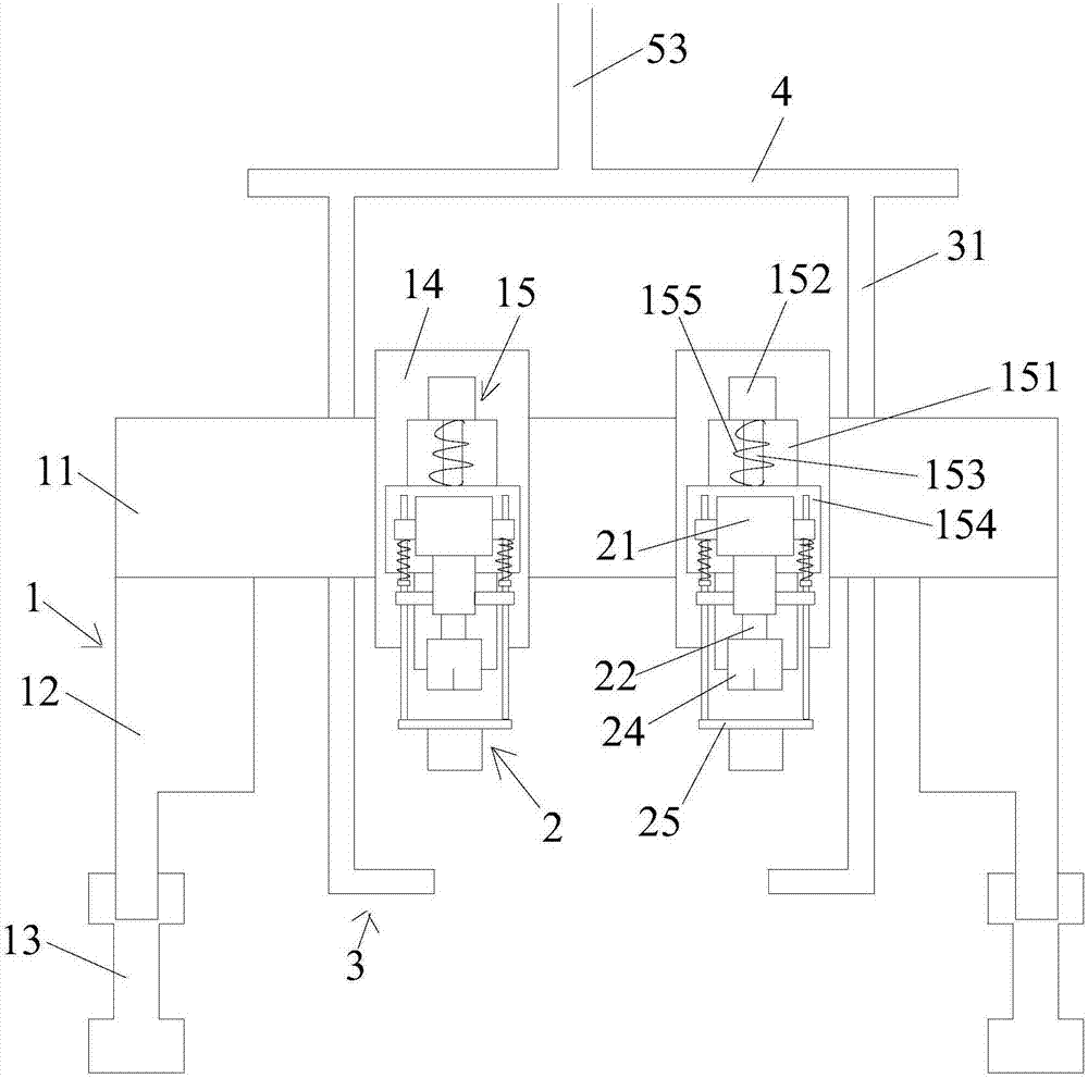
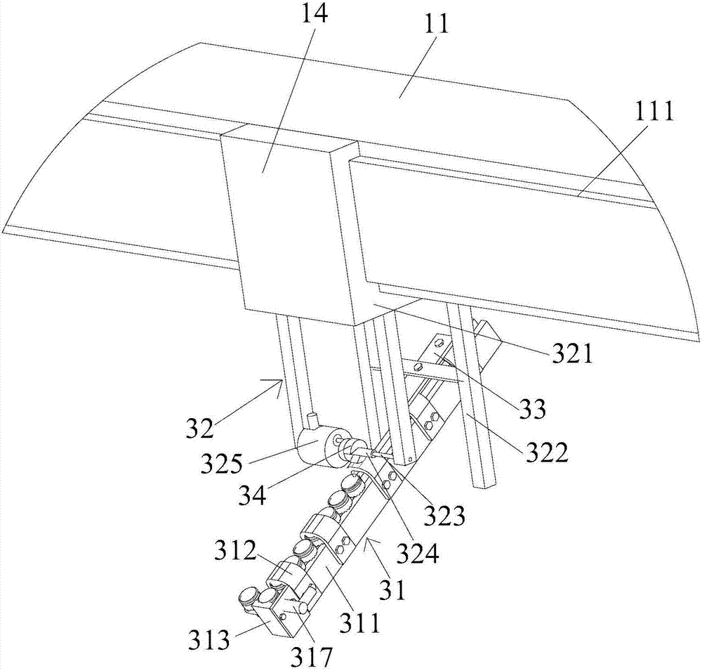
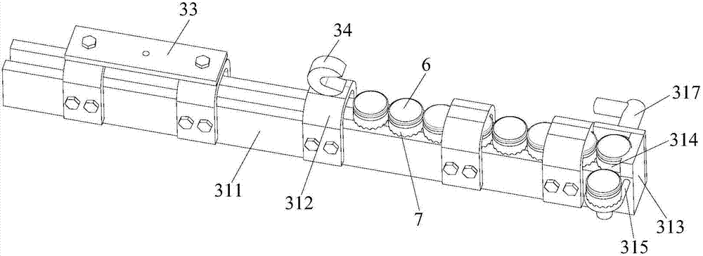
[0050] Such as figure 1 Shown: a device provided by the present invention for fully automatic stud welding of T-shaped welding studs, including a three-axis motion platform 1, several automatic welding guns 2, several automatic feeding mechanisms 3, and T-shaped welding studs with ceramic rings The conveying track 4 and the automatic socket mechanism of the T-shaped welding stud and the ceramic ring; the automatic welding gun 2 is arranged on the three-axis motion platform 1, and the up-down, left-right and front-back movement of the automatic welding gun 2 is realized through the three-axis motion platform 1, To achieve accurate positioning to the spot to be welded; each automatic welding gun 2 is equipped with an automatic feeding mechanism 3, and the automatic feeding mechanism 3 is connected to the three-axis motion platform 1, and can be moved synchronously with the automatic welding gun 2 through the three-axis motion platform 1 position, and the automatic feeding mechan...


PUM


Abstract

The invention discloses a device for realizing full-automatic stud welding of a T-type welding stud. The device comprises a three-axis moving platform, multiple automatic welding guns, multiple automatic feeding mechanisms, a conveying track for conveying the T-type welding stud sleeved by a ceramic ring and an automatic sleeving mechanism for the T-type welding stud and the ceramic ring, wherein the up-down, left-right and back-forth movement of the automatic welding gun is realized through the three-axis moving platform; the automatic feeding mechanisms can move left and right or back and forth; a feed port of each automatic feeding mechanism is connected with the conveying track for conveying the T-type welding stud sleeved by the ceramic ring; and a feed port of the conveying track is connected to an output track of the automatic sleeving mechanism for the T-type welding stud and the ceramic ring. By adopting the device disclosed by the invention, automatic sleeving of the T-type welding stud and the ceramic ring, automatic conveying of the T-type welding stud sleeved by the ceramic ring and automatic clamping and release of the T-type welding stud and the ceramic ring by the welding gun are realized for the first time; and in combination with the three-axis moving platform, full-automatic arc stud welding of the T-type welding stud is realized for the first time, and the welding efficiency and quality of the T-type welding stud are remarkably improved.

Description

technical field [0001] The invention relates to a stud welding device, in particular to a device for realizing full-automatic stud welding of T-shaped welding studs, and belongs to the technical field of stud welding equipment. Background technique [0002] T-shaped welding studs (also known as cylindrical head welding studs) are widely used as shear connectors (also known as shear keys) in steel structures and "steel-concrete" structures in construction and bridge construction. The stud welding method is planted and welded on steel beams, steel columns and other structures. A project (a high-rise building or a bridge) requires tens of thousands or even hundreds of thousands of T-shaped welding studs. According to statistics, the annual welding volume of T-shaped welding studs in Japan is 60 million, while the annual demand for T-shaped welding studs in steel structure buildings in my country is tens of millions. During the welding process, it is necessary to use a ceramic...

Claims


Application Information

Patent Timeline
Patent Type & Authority Patents(China)
IPC IPC(8): B23K9/20B23K9/32
CPCB23K9/206B23K9/32
Inventor 胡长建周茂臣李鹏程胡海波邓显红
Owner 胡长建
Learn More