Earthquake-resistant building support connecting structure and method

A technology for connecting structures and connecting flanges, which is applied in the direction of building components, building structures, buildings, etc., can solve the problems of connection failure, inconvenient disassembly and assembly, and easy cracks, etc., to achieve convenient installation and fixing, good seismic performance, The effect of structural stability

Active Publication Date: 2016-05-25
QIAO BUILDING MATERIALS (SHANGHAI) CO LTD
View PDF5 Cites 15 Cited by
  • Summary
  • Abstract
  • Description
  • Claims
  • Application Information

AI Technical Summary

Problems solved by technology

[0002] The existing building supports are usually connected by welding, so that the pipes cannot be reused, and the disassembly is inconvenient. The disassembly process is very time-consuming. Due to the rigid connection, cracks and other defects are prone to occur when subjected to external forces, resulting in connection failure

Method used


Image

  • Earthquake-resistant building support connecting structure and method

Examples


Embodiment 1

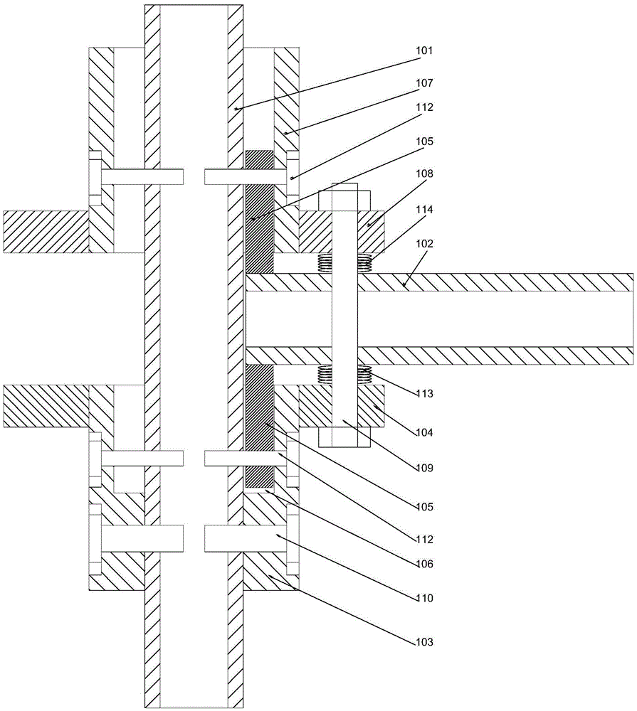
[0026] like figure 1 As shown, a connection structure for an earthquake-resistant building support includes a longitudinal steel pipe 101 and a transverse steel pipe 102 made of square steel. A supporting flange 104 is provided, a stepped groove 106 is provided on the inner wall of the upper end of the fixed sleeve 103, and snap-in parts 105 are respectively provided on the upper and lower ends of the end of the horizontal steel pipe 102, and the snap-in part 105 and the transverse steel pipe 102 are perpendicular to each other, the clamping part 105 at the lower part can be embedded in the stepped groove 106, and a through hole is provided on the transverse steel pipe 102, and the through hole The axis of the hole is parallel to the line connecting the two clamping parts 105, the support flange 104 is provided with a fixing hole, and the longitudinal steel pipe 101 is fitted with a moving sleeve 107, and the The fixed sleeve 103 can slide up and down along the longitudinal s...

Embodiment 2

[0032] On the basis of Embodiment 1, this embodiment also discloses a method for connecting earthquake-resistant building supports, including the following steps:

[0033] S1: Set the fixing sleeve 103 on the longitudinal steel pipe 101 so that it is fixed relative to the longitudinal steel pipe 101 and cannot move longitudinally;

[0034] S2: Put the fixing bolt 109 through the fixing hole on the support flange 104, and put the damping spring 113 on the fixing bolt 109;

[0035] S3: Connect the clamping part 105 at the lower end of the transverse steel pipe 102 into the stepped groove 106 inside the fixed sleeve 103, make the lower end surface of the transverse steel pipe 102 fit on the upper end surface of the lower damping spring 113, and make the lower end surface The clamping part 105 is clamped in the cavity between the stepped groove 106 and the outer wall of the longitudinal steel pipe 101;

[0036] S4: Put the upper damping spring 114 on the fixing bolt 109, so that ...


PUM


Abstract

The invention discloses an earthquake-resistant building support connecting structure which comprises a longitudinal steel pipe and a transverse steel pipe which are made of square steel. A fixing sleeve is arranged on the longitudinal steel pipe. A supporting flange is arranged on the outer wall of the upper end of the fixing sleeve. A step groove is formed in the inner wall of the upper end of the fixing sleeve. Clamping parts are arranged on the upper end face and the lower end face of the tail end of the transverse steel pipe respectively and perpendicular to the transverse steel pipe. The clamping part on the lower side can be embedded in the step groove. A through hole is formed in the transverse steel pipe. The axis of the through hole is parallel to the connecting line of the two clamping parts. Fixing holes are formed in the supporting flange. The longitudinal steel pipe is sleeved with a movable sleeve. The stable connection structure can be formed by the longitudinal steel pipe and the transverse steel pipe, so the longitudinal steel pipe and the transverse steel pipe can not move relatively in the horizontal direction or the vertical direction, the structure is stable, and connection is reliable.

Description

technical field [0001] The invention relates to an earthquake-resistant building support connection structure and a connection method thereof. Background technique [0002] The existing building supports are usually connected by welding, so that the pipes cannot be reused, and the disassembly is inconvenient. The disassembly process is very time-consuming. Due to the rigid connection, cracks and other defects are prone to occur when subjected to external forces, resulting in Connection failed. Contents of the invention [0003] The object of the present invention is to provide a connection structure and connection method for anti-seismic building supports, which can improve the problems existing in the prior art, and make the longitudinal steel pipe and the horizontal steel pipe form a stable connection structure, so that the longitudinal steel pipe and the horizontal steel pipe can be connected horizontally and vertically The vertical direction can not move relatively, t...

Claims


Application Information

Patent Timeline
Patent Type & Authority Applications(China)
IPC IPC(8): E04B1/24E04B1/98E04B1/58
CPCE04B1/24E04B1/2403E04B1/98E04B2001/2418
Inventor 倪黄女
Owner QIAO BUILDING MATERIALS (SHANGHAI) CO LTD
Why Eureka
Try Eureka