Anti-rotating insulating support and anti-rotating method thereof

A technology of insulating support and anti-rotation, applied in the direction of fixed/insulated contact components, etc., to achieve the effects of good electrical transmission performance, enhanced fastness, and good fastness

Active Publication Date: 2011-08-31
BEIJING LEAGUESUN ELECTRONICS
View PDF0 Cites 0 Cited by
  • Summary
  • Abstract
  • Description
  • Claims
  • Application Information

AI Technical Summary

Problems solved by technology

The insulating support consists of three layers of metal inner sleeve, intermediate medium and metal outer ring from the inside to the outside. The three layers of the insulating support commonly used are tubular components, and the inner and outer rings of the cross-section of each tubular component are Complete circle, this structure makes the tightness between the three-layer parts poor, and the relative rotation between two parts often occurs. The misalignment caused by the mutual rotation between the three-layer parts will make the electromagnetic wave transmit in the inner cavity of the outer conductor. The performance index is affected, and at the same time, it will cause wear to the intermediate medium, reduce its service life, and be prone to danger, so there are potential safety hazards
Insulation support can also be made by injection molding process. The liquid medium is injected into the metal inner sleeve and the metal outer ring by using a medium mold, and plasticized, flowed and cooled into a solid under certain external conditions. Although the three insulating supports produced by this injection molding process The fastness between layer parts will be better, but the injection molding process has high process costs, and the requirements for temperature, molding cycle and other process processes are relatively complicated, so its application is greatly restricted

Method used


Image

  • Anti-rotating insulating support and anti-rotating method thereof
  • Anti-rotating insulating support and anti-rotating method thereof
  • Anti-rotating insulating support and anti-rotating method thereof

Examples


Embodiment Construction

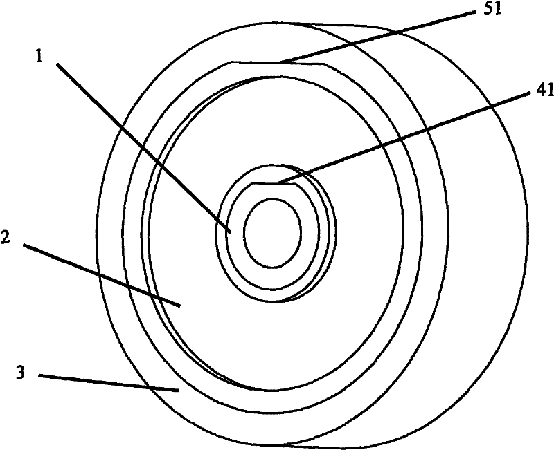
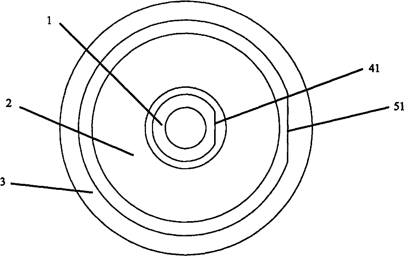
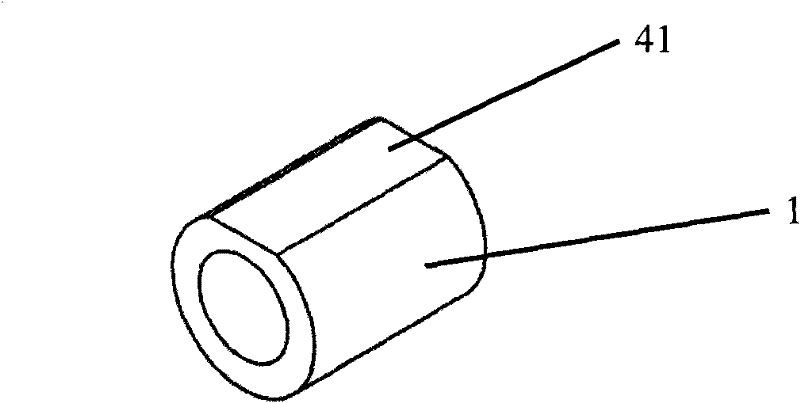
[0028] figure 1 It is a structural schematic diagram of a preferred embodiment of the anti-rotation insulating support of the present invention, figure 2 It is a schematic diagram of its front structure. The anti-rotation insulating support includes a metal inner sleeve 1, an intermediate medium 2, and a metal outer ring 3 connected from the inside to the outside. The inner ring of the cross section of the metal inner sleeve 1 is circular and cooperates with the central conductor , the outer surface of the metal inner sleeve 1 has a cut inner sleeve first platform 41 along the tube length direction, the inner sleeve first platform 41 is parallel to the central axis of the metal inner sleeve 1 and penetrates both horizontally and vertically, and the metal inner sleeve 1 The outer ring of the cross-section is circular, and its circular angle is between 50° and 60°, which can also be seen in detail Figure 3a The schematic diagram of the three-dimensional structure of the meta...


PUM


Abstract

The invention relates to an anti-rotating insulating support and an anti-rotating method thereof. The anti-rotating method is characterized in that the outer side surface of a metal inner sleeve and the inner side surface of a middle medium are respectively provided with a first platform mutually fit along the direction of the pipe length so as to lead one part of a curve surface attached tightlybetween the metal inner sleeve and the middle medium to be attached tightly in a plane; an outer ring of the part of the cross section of the metal inner sleeve, provided with the first platform, is a round flaw shape of a round flaw angle between 15 degrees to 90 degrees; the outer side surface of the middle medium and the inner side surface of the metal outer ring are respectively provided witha second platform fit along the direction of the pipe length so as to lead one part of a curve surface attached tightly between the middle medium and the metal outer ring to be attached tightly in a plane; and an outer ring of the part of the cross section of the middle medium, provided with the second platform, is a round flaw shape of a round flaw angle between 15 degrees to 60 degrees. The invention can prevent relative rotation among three-layer parts of the insulating support, simultaneously has simple method, easy processing, low cost and reliable work.

Description

technical field [0001] The invention relates to an insulating support part in a precision coaxial cable connector used in radio frequency and microwave transmission technology, in particular to an anti-rotation insulating support and an anti-rotation method thereof. Background technique [0002] Precision coaxial cable connectors used in radio frequency and microwave transmission technologies usually include components such as center conductors, insulating supports and outer conductors, and center conductors are usually divided into two parts, such as center conductor A and center conductor B, usually in The center conductor A is covered with an insulating support, and then inserted into the center conductor B and then screwed or welded into one body, and then the outer conductor is installed, and the electromagnetic wave is transmitted in the inner cavity of the outer conductor. The insulating support consists of three layers of metal inner sleeve, intermediate medium and ...

Claims


Application Information

Patent Timeline
Patent Type & Authority Patents(China)
IPC IPC(8): H01R13/40
Inventor 孙晓峰
Owner BEIJING LEAGUESUN ELECTRONICS
Why Eureka
Try Eureka