Foldable support mechanism

A technology of folding supports and lugs, which is applied in the direction of supporting machines, mechanical equipment, machine tables/brackets, etc., can solve the problems of small supporting force of supporting equipment, heavy supporting force, and difficulty in supporting large-tonnage mechanical parts, etc., to achieve Convenient packing and carrying, stable and reliable support, fast and stable recovery process

Inactive Publication Date: 2016-05-25
CHANGZHI QINGHUA MACHINERY FACTORY +1
View PDF5 Cites 4 Cited by
  • Summary
  • Abstract
  • Description
  • Claims
  • Application Information

AI Technical Summary

Problems solved by technology

[0002] In recent years, the field of mechanical maintenance has been greatly developed. The formation of maintenance ideas has promoted the effective utilization of machinery, extended service life, and energy conservation. However, maintenance of large-tonnage mechanical part

Method used


Image

  • Foldable support mechanism
  • Foldable support mechanism
  • Foldable support mechanism

Examples


Embodiment 1

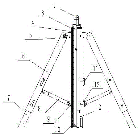
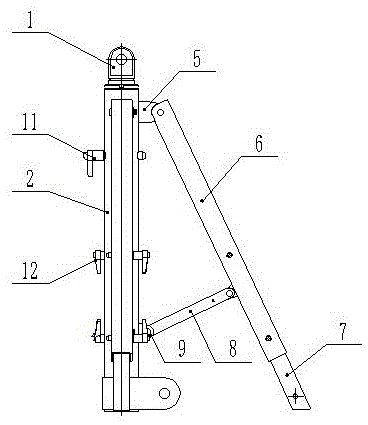
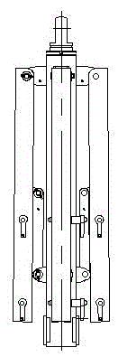
[0023] Such as Figure 1-Figure 4 As shown, the foldable support mechanism includes a telescopic rod 1, a fixed rod 2, an end cover 3, a composite bearing 4, at least three hollow outriggers 6, at least three movable outriggers 7, a pull rod 8, a support ring 10, a first L Type quick-release pin 11, the second L-shaped quick-release pin 12, the telescopic rod 1 and the fixed rod 2 are vertically arranged, and the fixed rod 2 with the upper end open and the lower end closed is set on the outside of the telescopic rod 1, and the support The ring 8 is arranged at the lower end of the telescopic rod 1, the composite bearing 4 and the end cap 3 are arranged at the upper end of the telescopic rod 1, and the end cap 3 is arranged above the composite bearing 4 and below the head of the telescopic rod 1 to close the upper end of the fixed rod 2 A plurality of upper lugs 5 corresponding to the legs 6 are evenly arranged on the upper part of the outer wall of the fixed rod 2, a plurality...

Embodiment 2

[0030] Such as Figure 1-Figure 4 As shown, the foldable support mechanism includes a telescopic rod 1, a fixed rod 2, an end cover 3, a composite bearing 4, at least three hollow outriggers 6, at least three movable outriggers 7, a pull rod 8, a support ring 10, a first L Type quick-release pin 11, the second L-shaped quick-release pin 12, the telescopic rod 1 and the fixed rod 2 are vertically arranged, and the fixed rod 2 with the upper end open and the lower end closed is set on the outside of the telescopic rod 1, and the support The ring 8 is arranged at the lower end of the telescopic rod 1, the composite bearing 4 and the end cap 3 are arranged at the upper end of the telescopic rod 1, and the end cap 3 is arranged above the composite bearing 4 and below the head of the telescopic rod 1 to close the upper end of the fixed rod 2 A plurality of upper lugs 5 corresponding to the legs 6 are evenly arranged on the upper part of the outer wall of the fixed rod 2, a plurality...


PUM


Abstract

The invention relates to a foldable support mechanism, belonging to the technical field of a support device for repairing and maintaining large-tonnage machinery parts and components, and aiming at providing a support device which not only is capable of supporting the large-tonnage machinery parts and components, but also is convenient to carry. The technical scheme of the foldable support mechanism is as follows: a telescopic rod and a fixing rod are vertically arranged, an opening is formed in the upper end of the fixing rod, the lower end of the fixing rod is closed, and the fixing rod is sleeved outside the telescopic rod; a support ring is arranged at the lower end of the telescopic rod; a composite bearing and an end cover are arranged at the upper end of the telescopic rod; the end cover is used for closing the upper end of the fixing rod; a plurality of upper support lugs corresponding to support legs are evenly arranged at the upper part of the outer wall of the fixing rod, a plurality of quick-release pin connecting holes connected with first L-shaped quick-release pins are formed in the middle of the outer wall of the fixing rod, a plurality of lower support lugs corresponding to the support legs are evenly arranged at the lower part of the outer wall of the fixing rod; the upper ends of the support legs are hinged with the upper support lugs, the lower ends of the support legs are hinged with one ends of pull rods, and the other ends of the pull rods are hinged with the lower support lugs; movable support legs are connected at the lower ends of the support legs in a sliding way. The foldable support mechanism is used for supporting the large-tonnage machinery parts and components.

Description

technical field [0001] A foldable support mechanism belongs to the technical field of support devices for repairing and maintaining large-tonnage mechanical parts. Background technique [0002] In recent years, the field of mechanical maintenance has been greatly developed. The formation of maintenance ideas has promoted the effective utilization of machinery, extended service life, and energy conservation. However, maintenance of large-tonnage mechanical parts often requires Stable and effective support equipment, the existing support equipment is too bulky and inconvenient to carry, and the support equipment that is easy to carry has a relatively small support force, which is difficult to meet the support of large-tonnage mechanical parts. Contents of the invention [0003] The technical problem to be solved by the present invention is to provide a support device that can support large-tonnage mechanical parts and is easy to carry. [0004] In order to solve the above-m...

Claims


Application Information

Patent Timeline
IPC IPC(8): F16M11/32
CPCF16M11/32
Inventor 张丽娜张月红刘喜东武廷金新卫雄飞张晟张艳云韩晓于杰马雷鹏潘洑满赵子剑
Owner CHANGZHI QINGHUA MACHINERY FACTORY
Why Eureka
Try Eureka