

High voltage lead angle error influence testing device and testing method thereof
A high-voltage lead wire and angle error technology, which is applied in the direction of measuring devices, instruments, and measuring electrical variables, can solve problems such as difficulties in on-site verification, poor response characteristics of transformers, and difficulty in satisfying fast and accurate actions of relay protection, etc. Difficulty, operability improvement effect
Inactive Publication Date: 2016-05-25
STATE GRID CORP OF CHINA +1
View PDF3 Cites 0 Cited by
- Summary
- Abstract
- Description
- Claims
- Application Information
AI Technical Summary
Problems solved by technology
Electric field simulation shows that for a 1000kV CVT, the capacitive current flowing from the high-voltage arm of the voltage divider into the ground can reach 20mA, causing significant measurement errors
Measures are usually taken to increase the main capacitance of the voltage divider to reduce the influence of stray currents, but even if the capacitance is increased to 10000pf, the accuracy level of UHV CVT is still difficult t
Method used
View moreImage
Smart ImageViewing Examples

Examples
 PUM
| Property | Measurement | Unit |
|---|---|---|
| Diameter | aaaaa | aaaaa |
Abstract
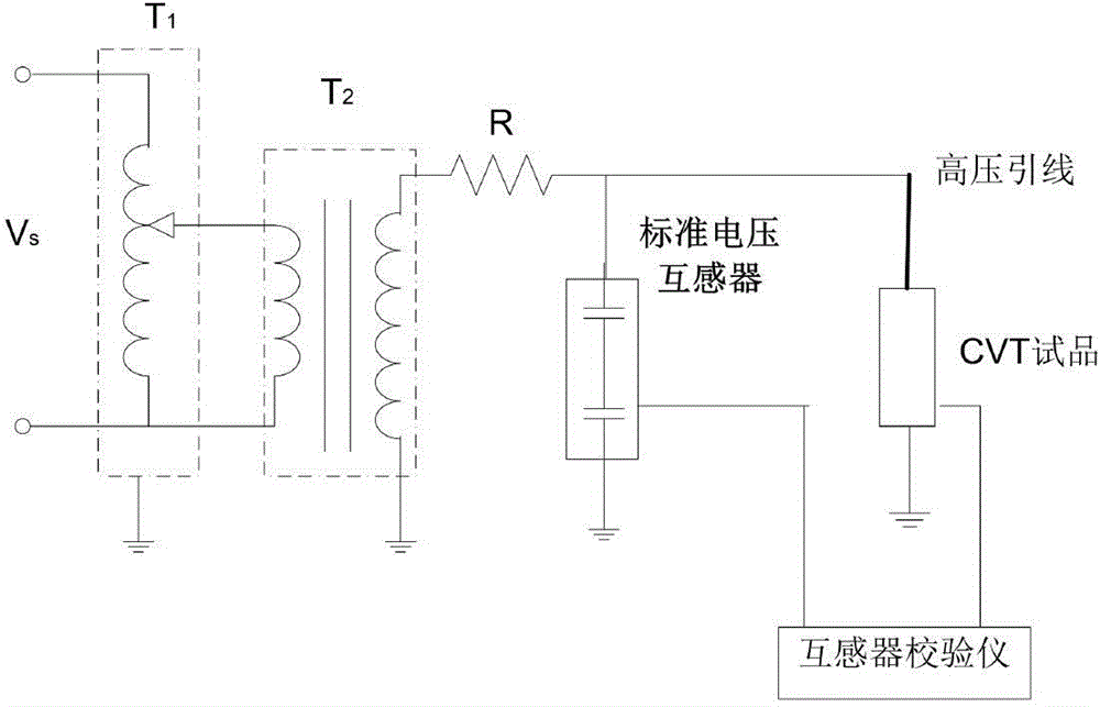
The invention relates to a high voltage lead angle error influence testing device and a testing method thereof. The device comprises a voltage regulator, a test transformer, a standard transformer, an equipotential shielded capacitor voltage transformer (CVT) test sample and a high voltage lead, wherein the primary side of the test transformer is connected with the voltage regulator, one end of the secondary side is grounded, and the other end of the secondary side is connected with one end of a current limiting resistor R; the other end of the current limiting resistor R is respectively connected with the primary side of the standard voltage transformer and the primary side of the equipotential shielded capacitor voltage transformer test sample; the secondary side of the standard voltage transformer and the secondary side of the equipotential shielded capacitor voltage transformer test sample are both connected with a transformer calibrator; and an angle is formed between the high voltage lead and the axis of the equipotential shielded capacitor voltage transformer test sample. Conditions of different high voltage lead connection modes can be simulated successfully, the accuracy of the CVT in the conditions is verified to still achieve requirements of a high-precision accuracy grade, and in the above conditions, the generated error changes are smaller than those of a CVT with a traditional structure.
Description
technical field [0001] The invention relates to a power system transformer device and a method thereof, in particular to a high-voltage lead wire angle error influence test device and a test method thereof. Background technique [0002] With the engineering application of UHV (AC 1000kV and above) transmission technology, the accurate measurement of UHV grid voltage has become a key technical problem to be studied and solved. The power frequency high voltage measurement devices widely used in the power system mainly include electromagnetic voltage transformers and capacitive voltage transformers (both of which are passive voltage measurement systems), which can basically meet the requirements of 500kV and below voltage level voltage measurement and Requirements for relay protection. Photoelectric voltage transformers and electronic voltage transformers (both of which are active voltage measurement systems) are still in the process of research and development and trial opera...
Claims
Login to View More Application Information
Patent Timeline
 IPC IPC(8): G01R35/02
Inventor 查鲲鹏董巍李志麒高冲
Owner STATE GRID CORP OF CHINA