
Test fixture used for three-directional vibration test of thin and long elbow pipe and test method of test fixture

A test fixture and vibration test technology, used in vibration testing, machine/structural component testing, measuring devices, etc., can solve the problems of inability to conduct tests, reduce the utilization rate of shaking tables, etc., to save test costs, improve work efficiency, Eliminate the effect of extra load

Inactive Publication Date: 2015-04-08
SHANGHAI SPACE PRECISION MACHINERY RES INST
View PDF6 Cites 12 Cited by
  • Summary
  • Abstract
  • Description
  • Claims
  • Application Information

AI Technical Summary

Problems solved by technology

However, when the weight of the sliding table is close to or even greater than that of the specimen, and the test magnitude is large, most of the thrust of the shaking table is consumed by the exciting sliding table, which greatly reduces the utilization rate of the shaking table, and even the test cannot be carried out due to the limitation of the thrust.

Method used


Image

  • Test fixture used for three-directional vibration test of thin and long elbow pipe and test method of test fixture
  • Test fixture used for three-directional vibration test of thin and long elbow pipe and test method of test fixture
  • Test fixture used for three-directional vibration test of thin and long elbow pipe and test method of test fixture

Examples


Embodiment Construction

[0028] The following is a detailed description of the embodiments of the present invention: this embodiment is implemented on the premise of the technical solution of the present invention, and provides detailed implementation methods and specific operation processes. It should be noted that those skilled in the art can make several modifications and improvements without departing from the concept of the present invention, and these all belong to the protection scope of the present invention.

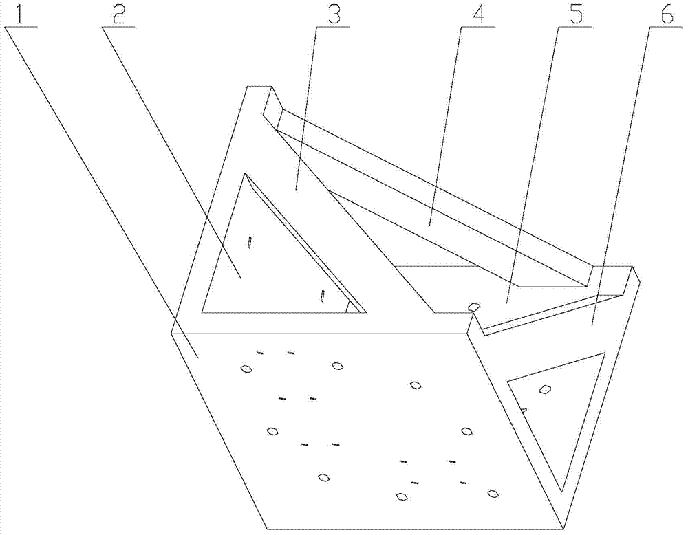
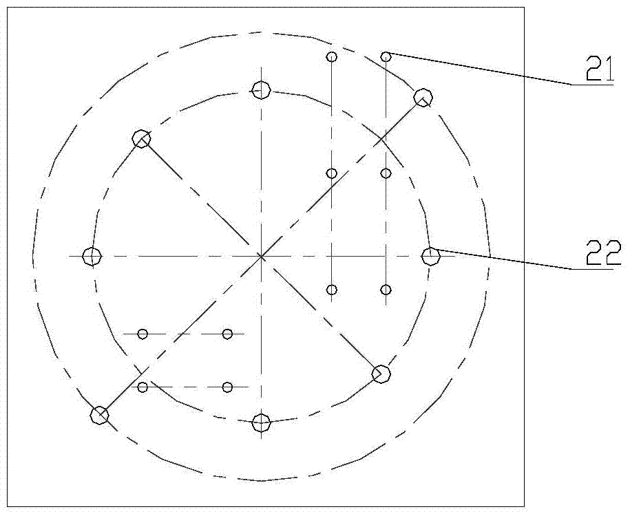
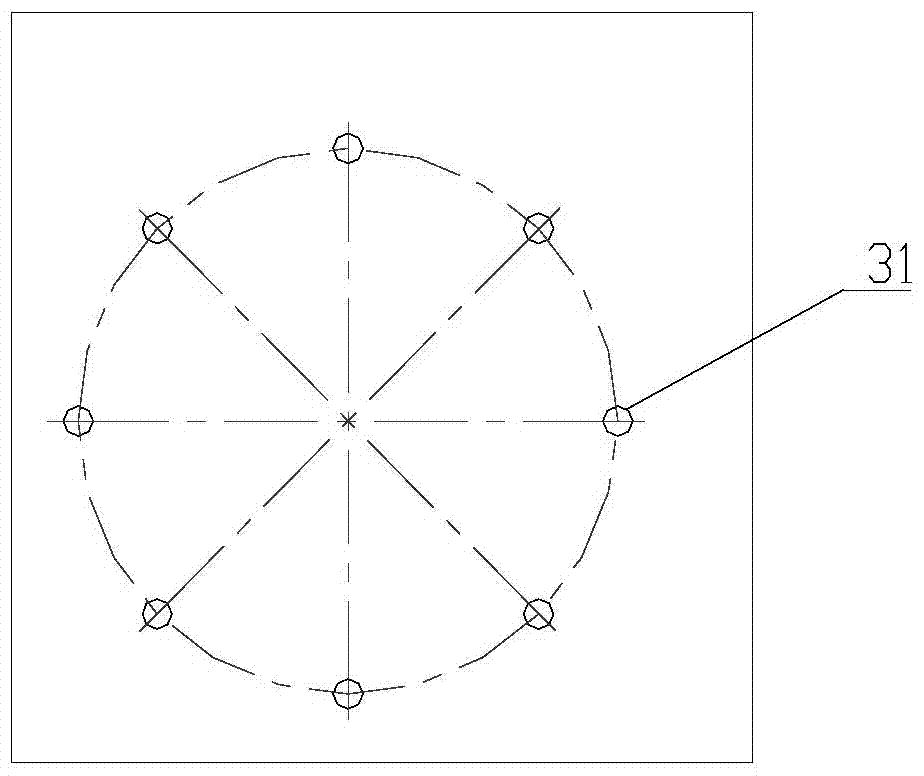
[0029] Please also see Figure 1 to Figure 5 .

[0030] This embodiment provides a test fixture for the three-way vibration test of a slender bent pipe, including an X-direction mounting plate, a Y-direction mounting plate and a Z-direction mounting plate, and the X-direction mounting plate, Y-direction mounting plate and Z-direction mounting plate Two of the mounting plates are vertically connected to each other to form three orthogonal planes; between the X-direction mounting plate a...


PUM


Abstract

The invention discloses a test fixture used for a three-directional vibration test of a thin and long elbow pipe. The test fixture comprises an X-directional mounting plate, a Y-directional mounting plate and a Z-directional mounting plate, wherein the X-directional mounting plate, the Y-directional mounting plate and the Z-directional mounting plate are vertically connected two by two; reinforcing plates are further arranged between the X-directional mounting plate and the Y-directional mounting plate, between the Y-directional mounting plate and the Z-directional mounting plate, and between the X-directional mounting plate and the Z-directional mounting plate; test piece mounting holes I and vibration platform mounting holes I are formed in the X-directional mounting plate; vibration platform mounting holes II are formed in the Y-directional mounting plate; test piece mounting holes II and vibration platform mounting holes III are formed in the Z-directional mounting plate. Meanwhile, the invention provides a test method. According to the test fixture, a test piece only needs to be mounted in one step through the conversion of a self mounting surface, then the vibration test in three directions of the test pieces with two types can be finished respectively; the dependence on a sliding platform is avoided; the requirements on the thrust of a vibration platform are reduced; the test efficiency is improved and the test cost is reduced.

Description

technical field [0001] The invention relates to the technical field of vibration test methods, in particular to a test fixture and a test fixture for three-way vibration tests of slender bent pipes that can be used for three-way vibration tests without a sliding table for two types of slender bent pipes. method. Background technique [0002] As an auxiliary equipment for horizontal vibration tests, the sliding table plays an important role in three-way vibration tests, especially when supporting large test pieces (such as complete machines), it is almost indispensable. However, when the weight of the sliding table is close to or even greater than that of the specimen, and the test level is large, most of the thrust of the shaking table is consumed by the exciting sliding table, which greatly reduces the utilization rate of the shaking table, and even the test cannot be carried out due to the limitation of the thrust. Therefore, in this case, it is necessary to improve the t...

Claims


Application Information

Patent Timeline
Patent Type & Authority Applications(China)
IPC IPC(8): G01M7/06
Inventor 高海慧吴欣凯庄建宇吴永平傅烨沈晨晨
Owner SHANGHAI SPACE PRECISION MACHINERY RES INST
Learn More