Hybrid bearing turbomachine

a turbomachine and hybrid technology, applied in the direction of machines/engines, mechanical apparatus, liquid fuel engines, etc., can solve the problems of high power consumption of hydrostatic bearings, high cost and complexity of magnetic bearings, scaling problems of foil bearings that make large machines unfavorable, etc., to achieve the effect of reducing thrust loads

Active Publication Date: 2016-01-12
RTX CORP
View PDF27 Cites 30 Cited by
  • Summary
  • Abstract
  • Description
  • Claims
  • Application Information

AI Technical Summary

Benefits of technology

[0004]A turbomachine includes a housing and a rotatable shaft, where at least a portion of the rotatable shaft is located in the housing. The turbomachine also includes a magnetic thrust bearing that axially positions the rotatable shaft and a radial bearing that centers the rotatable shaft. The turbomachine includes a flexure including a first portion secured to the housing and a second portion axially moveable relative to the first portion. The second portion of the flexure is connected to the radial bearing, and the second portion moves axially to eliminate thrust loads on the radial bearing and allow the magnetic thrust bearing to carry axial loads.
[0006]A method of reducing thrust loads on a radial bearing of a turbomachine includes the steps of rotating a shaft located in a housing of the turbomachine and axially positioning the shaft with a magnetic thrust bearing. The method further includes the steps of securing a first portion of a flexure to the housing and axially moving a second portion of the flexure relative to the first portion of the flexure to axially translate the radial bearing to eliminate axial loads on the radial bearing and allow by the magnetic thrust bearing to carry axial loads.

Problems solved by technology

Disadvantages of current turbomachines are the expense and complexity of the magnetic bearing, as well as scaling problems with foil bearings that makes large machines unfeasable.
Additionally, the power consumption of hydrostatic bearings can be high, and when operated under high loads, the reliability of ball bearings can decrease.

Method used


Image

  • Hybrid bearing turbomachine
  • Hybrid bearing turbomachine
  • Hybrid bearing turbomachine

Examples


Embodiment Construction

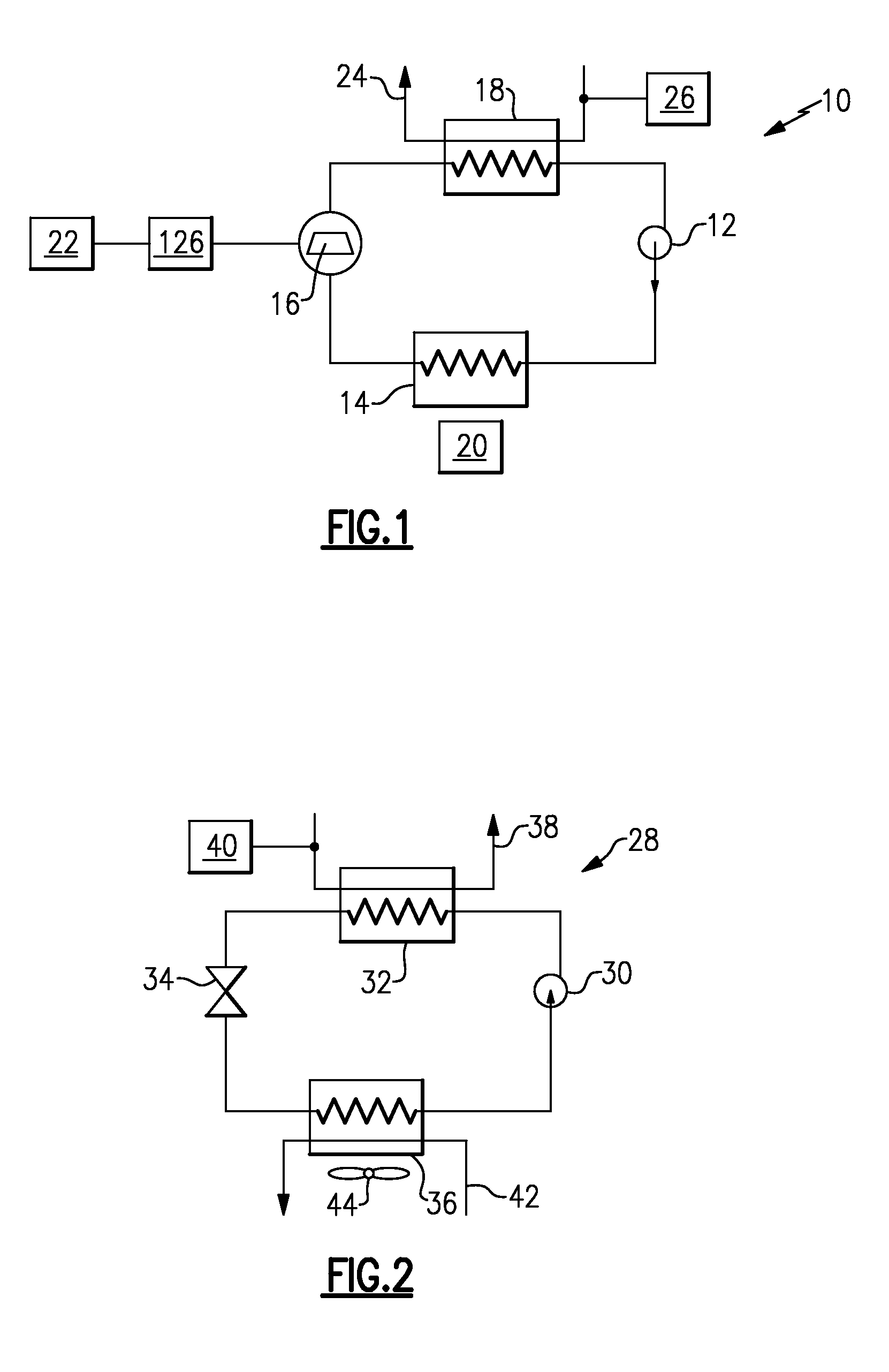
[0014]FIG. 1 illustrates an example organic rankine cycle 10 that converts heat into work. The organic rankine cycle 10 includes a pump 12, an evaporator 14, a turbine 16, and a condenser 18. An organic fluid circulates through the closed circuit system. The fluid flows as a liquid through the pump 12 and is pumped from a low pressure to a high pressure. The high pressure liquid then flows through the evaporator 14, where the fluid is heated and boiled at a constant pressure by an external heat source 20, and the fluid becomes a vapor. The vapor flows through the turbine 16 and is expanded, generating power. The shaft power generated by the turbine 16 is fed to a generator 126, which converts the shaft power to electrical power which is provided to an electric power grid 22 or load. The temperature and the pressure of the vapor decreases. The vapor then enters the condenser 18, where the fluid rejects heat to a cooling medium 24, heating the cooling medium 24. A pump or fan 26 moves...


PUM


Abstract

A turbomachine includes a housing and a rotatable shaft, where at least a portion of the rotatable shaft is located in the housing. The turbomachine also includes a magnetic thrust bearing that axially positions the rotatable shaft and a radial bearing that centers the rotatable shaft. The turbomachine includes a flexure including a first portion secured to the housing and a second portion axially moveable relative to the first portion. The second portion of the flexure is connected to the radial bearing, and the second portion moves axially to eliminate thrust loads on the radial bearing and allow the magnetic thrust bearing to carry axial loads.

Description

BACKGROUND OF THE INVENTION[0001]High speed turbomachines can employ various types of bearings. For example, rolling element bearings, magnetic bearings, foil bearings or fluid film bearings can be employed.[0002]Oil free turbomachines provide many benefits. For one, there are more effective heat transfer surfaces and no issues with oil stability or contamination. Oil free turbomachines have employed magnetic bearings, hydrostatic bearings, or foil bearings. Turbomachines have also been developed using refrigerant lubricated roller bearings and hydrostatic bearings.[0003]Disadvantages of current turbomachines are the expense and complexity of the magnetic bearing, as well as scaling problems with foil bearings that makes large machines unfeasable. Additionally, the power consumption of hydrostatic bearings can be high, and when operated under high loads, the reliability of ball bearings can decrease.SUMMARY OF THE INVENTION[0004]A turbomachine includes a housing and a rotatable shaf...

Claims


Application Information

Patent Timeline
Patent Type & Authority Patents(United States)
IPC IPC(8): F04D29/58F04D29/051F04D29/058F04D29/059
CPCF04D29/051F04D29/058F04D29/059F16C39/06F16C19/06F16C19/54F16C25/083F16C32/0476F16C2360/00F16C2380/26F16C2360/44F16C2226/50
Inventor JONSSON, ULF J.BIEDERMAN, BRUCE P.COGSWELL, FREDERICK J.
Owner RTX CORP
Why Eureka
Try Eureka