PxM antenna with improved radiation characteristics over a broad frequency range

a radiation characteristic and broad frequency range technology, applied in the field of antennas, can solve the problems of high inefficiency of prior art designs, and achieve the effects of improving radiation efficiency, reducing loss, and increasing efficiency and operating frequency bandwidth

Inactive Publication Date: 2008-06-17
TDK CORPARATION
View PDF8 Cites 30 Cited by
  • Summary
  • Abstract
  • Description
  • Claims
  • Application Information

AI Technical Summary

Benefits of technology

[0014]The problems outlined above may be in large part addressed by an improved P×M antenna design that exhibits lower loss, and higher efficiency and operating frequency bandwidth over that provided by conventional P×M antenna designs. The P×M antenna design described herein increases radiation efficiency by eliminating the internal resistive load. Instead of employing an internal load as was done in previous designs, the P×M antenna design described herein improves broadband impedance matching between the electric and magnetic radiators of a P×M antenna by providing the radiators with a tapered, folded and / or end-loaded configuration. Broadband impedance matching may be further improved through the use of a predominantly reactive matching network, if necessary. Various methods for forming an improved P×M antenna are also contemplated herein.
[0016]As used herein, a “predominantly lossy” element may be described as any load that introduces a substantial amount of “loss” through resistive, dielectric or magnetic means. In many prior art designs, resistive loads were included between the conductive feed and ground plane to reduce reflections caused by unmatched magnetic and electric radiators. Because resistive loads tend to introduce a significant amount of loss, the prior art designs suffered from highly inefficient operation. A reactive load, on the other hand, introduces substantially no loss, and therefore, may be used for decreasing the difference between the input impedances of the magnetic and electric radiators without decreasing the radiation efficiency of the P×M antenna.
[0018]In some embodiments, the electric and magnetic radiators may be provided with a tapered configuration for improving input impedance matching for increasing the range of operating frequencies over which the desired P×M radiation pattern is maintained. For example, a shape of the slot antenna may resemble a bow-tie shape, whereas a shape of the monopole antenna may resemble a conical or triangular shape. Alternative shapes are also contemplated for the tapered monopole and slot antennas. Regardless of exact shape, the conductive feed may be formed from a transmission line spaced above the ground plane. To improve impedance matching between the tapered radiators, the transmission line may terminate in a flared section, which may be coupled to the ground plane via one or more predominantly reactive elements. A reactive matching network may or may not be used with the tapered monopole-slot configuration.

Problems solved by technology

Because resistive loads tend to introduce a significant amount of loss, the prior art designs suffered from highly inefficient operation.

Method used


Image

  • PxM antenna with improved radiation characteristics over a broad frequency range
  • PxM antenna with improved radiation characteristics over a broad frequency range
  • PxM antenna with improved radiation characteristics over a broad frequency range

Examples


Embodiment Construction

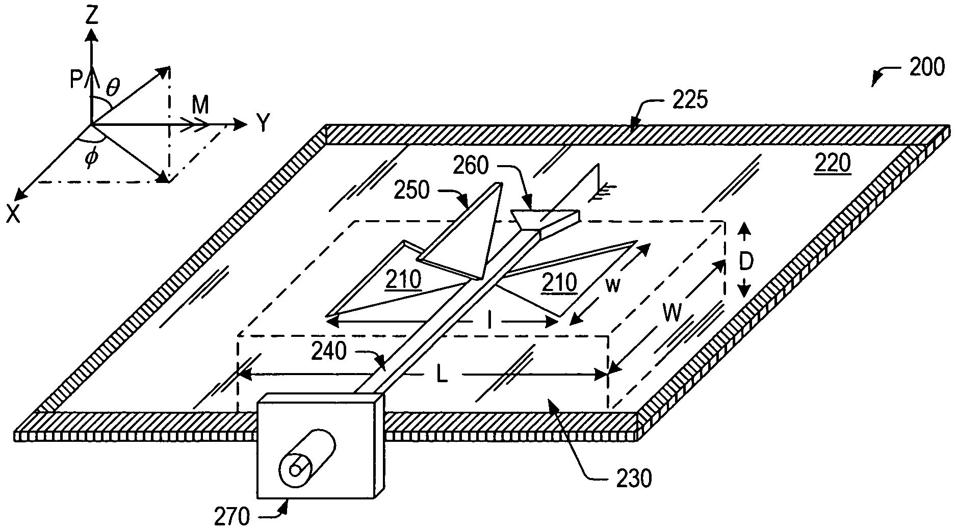
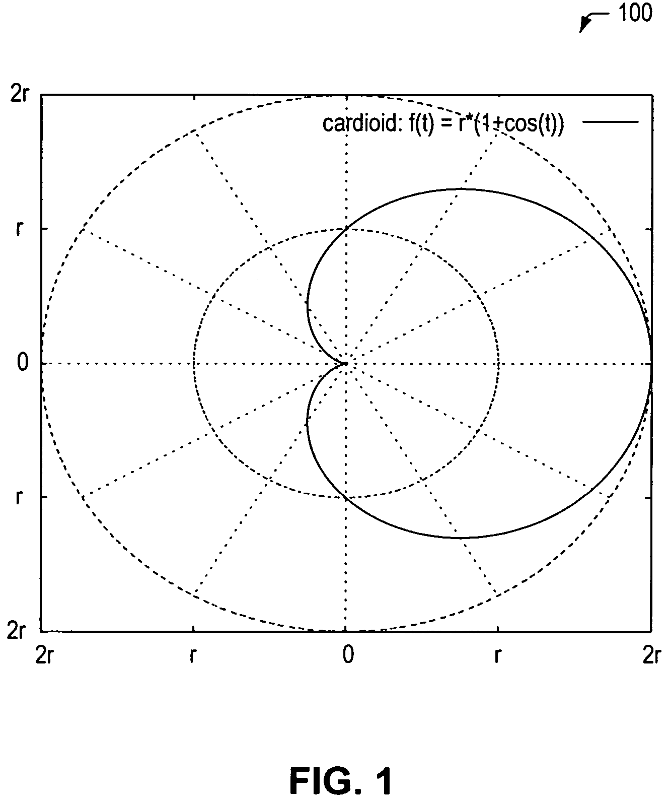
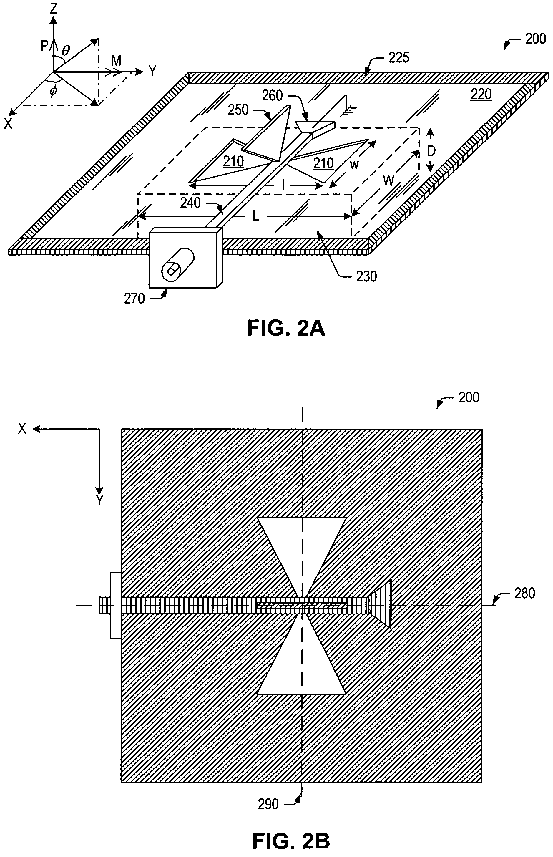
[0031]P×M antennas, so called because they are derived from an orthogonal combination of electric and magnetic radiators, possess several desirable characteristics including, but not limited to, a useful radiation pattern and relatively broad impedance bandwidth for a given electrical size. One form of the P×M antenna exhibits the radiation pattern of a hypothetical Huygens source. The radiation pattern, also referred to as the Ludwig-3 pattern, is a linearly-polarized unidirectional pattern comprised of a cardioid of revolution about the axis of maximum radiation intensity, and falls into the class of so-called maximum directivity patterns. As used herein, a “cardioid” is described as the curve traced by a point on the circumference of a circle rolling completely around another circle of fixed radius (r), and has the general equation of:

ρ=r*(1+cos θ)   (EQ.3)

in polar coordinates. A polar plot of a cardioid-shaped radiation pattern 100 is shown in FIG. 1. In the foregoing discussion...


PUM


Abstract

A low-loss, high-efficiency, broadband antenna including both electric and magnetic dipole radiators is provided herein. The broadband antenna may be referred to as a “P×M antenna” and may generally include a ground plane; a magnetic radiator formed within the ground plane; a conductive feed arranged within a first plane, which is parallel to the ground plane; and an electric radiator arranged within a second plane, which is perpendicular to the ground plane and coupled at one end to the conductive feed. According to a particular aspect of the invention, the electric and magnetic radiators are substantially complementary to one another and are coupled for producing a P×M radiation pattern over a broad range of operating frequencies. One advantage of the P×M antenna described herein is that the complementary antenna elements are combined without the use of a lossy, resistive matching network, thereby increasing the efficiency with which the P×M radiation pattern is produced.

Description

BACKGROUND OF THE INVENTION[0001]1. Field of the Invention[0002]This invention relates to antennas and, more particularly, to a practical implementation of a low-loss, high-efficiency, broadband antenna incorporating both electric and magnetic radiating components.[0003]2. Description of the Related Art[0004]The following descriptions and examples are not admitted to be prior art by virtue of their inclusion within this section.[0005]A wide operating frequency range is currently used for purposes of communications, especially ultra-wideband (UWB) communications and electromagnetic compatibility (EMC) testing. For example, many commercial and military-based communication devices operate within the 3 MHz to 30 MHz “high frequency” (HF) band, the 30 MHz to 300 MHz “very high frequency” (VHF) band, and in some cases, lower portions of the 300 MHz to 3 GHz “ultra high frequency” (UHF) band. Advantages of these relatively low frequency bands include improved diffraction around and penetra...

Claims


Application Information

Patent Timeline
Patent Type & Authority Patents(United States)
IPC IPC(8): H01Q21/00H01Q11/02H01Q13/10H01Q9/38
CPCH01Q1/38H01Q9/285H01Q13/106H01Q1/24H01Q5/00
Inventor MCLEAN, JAMES S.
Owner TDK CORPARATION
Why Eureka
Try Eureka