Three-dimensional vector beam and generation method and apparatus thereof

A three-dimensional vector and light beam technology, which is applied in optics, optical components, instruments, etc., can solve the problems of increased inconvenience and fixed vector beam polarization distribution, and achieves the effects of simple structure, convenient operation and easy adjustment

Active Publication Date: 2016-05-25
BEIJING INSTITUTE OF TECHNOLOGYGY
View PDF5 Cites 17 Cited by
  • Summary
  • Abstract
  • Description
  • Claims
  • Application Information

AI Technical Summary

Problems solved by technology

However, although the above methods can generate vector beams well, the polarization distribution of the generated vector beams is fixed
In order to change the polarization distribution of the vector beam, it is necessary to add devices such as wave plates in the optical path, which increases the inconvenience of its practical application to a certain extent

Method used


Image

  • Three-dimensional vector beam and generation method and apparatus thereof
  • Three-dimensional vector beam and generation method and apparatus thereof
  • Three-dimensional vector beam and generation method and apparatus thereof

Examples


Embodiment 1

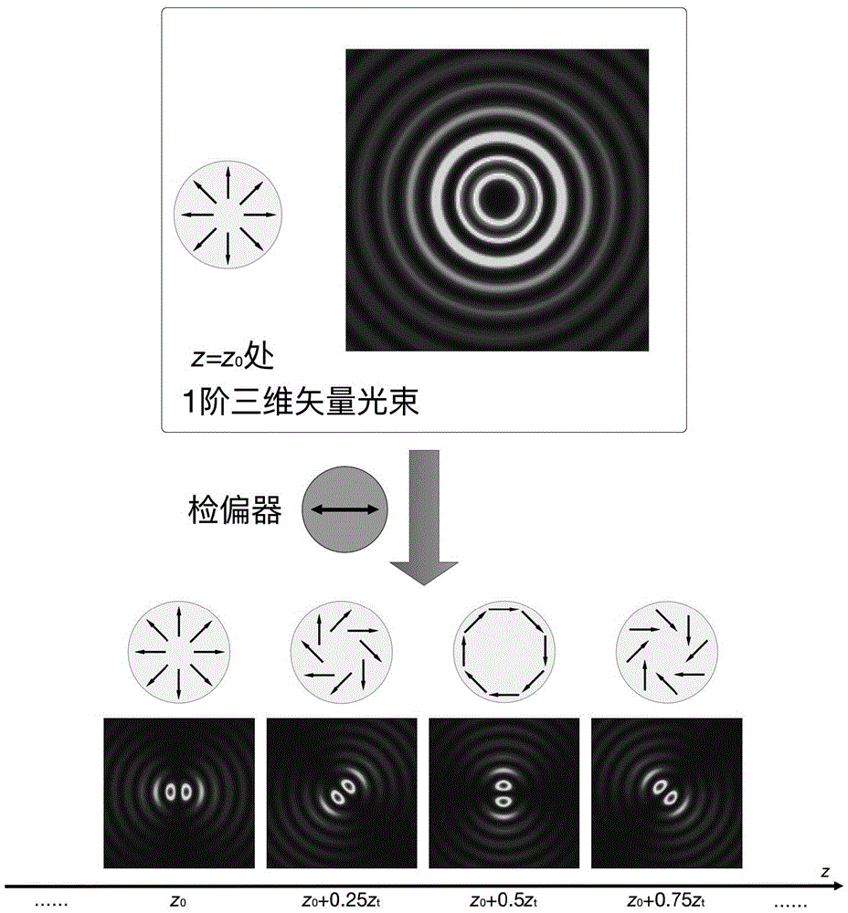
[0042] Embodiment 1: Generation of first-order three-dimensional vector beams.

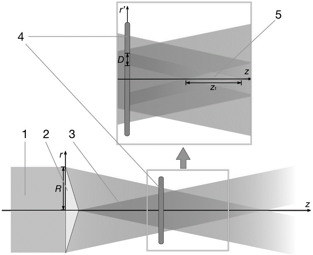
[0043] will be like Figure 4 The shown holographic grating after superimposing the axicon and the first-order spiral phase plate, and the holographic grating after superimposing the radial periodic phase and the second-order spiral phase plate are respectively loaded on the image 3 Two liquid crystal spatial light modulators in the shown setup. Turn on the laser light source, fix the CCD camera on the optical rail placed along the optical axis, and measure the three-dimensional vector beam at the initial position, 1 / 4 space period, 1 / 2 space period and 3 / 4 space period Such as Figure 5 shown in column 1. A rotatable polarizer is added in front of the CCD camera to detect the polarization state of the three-dimensional vector beam. When the polarizer is placed horizontally, 45° and vertically, the light spots received by the CCD camera are as follows: Figure 5 As shown in the last three co...

Embodiment 2

[0044] Embodiment 2: Generation of second-order three-dimensional vector beams.

[0045] will be like Image 6 The shown holographic grating after superimposing the axicon and the 2nd-order spiral phase plate, and the holographic grating after superimposing the radial periodic phase and the 4th-order spiral phase plate are respectively loaded on the image 3 Two liquid crystal spatial light modulators in the shown setup. Turn on the laser light source, fix the CCD camera on the optical rail placed along the optical axis, and measure the three-dimensional vector beam at the initial position, 1 / 4 space period, 1 / 2 space period and 3 / 4 space period Such as Figure 7 shown in column 1. A rotatable polarizer is added in front of the CCD camera to detect the polarization state of the three-dimensional vector beam. When the polarizer is placed horizontally, 45° and vertically, the light spots received by the CCD camera are as follows: Figure 7 As shown in the last three columns...


PUM


Abstract

The invention discloses a three-dimensional vector beam and a generation method and apparatus thereof. According to the provided three-dimensional vector beam, the optical field distribution is similar to the Bessel beam; and the cross section polarization-state distribution of the light beam changes with the change of the transmission distance and changes periodically. Within one spatial period, the polarization state of the beam changes from radial polarization to angular polarization alternately. Generated light beams can have various polarization-state distribution modes; and thus compared with the existing vector beam in single polarization-state distribution, the provided vector beam has the greater application value. According to the generation apparatus for the three-dimensional vector beam, generation of three-dimensional vector beams with different orders can be realized only by changing holographic grating loaded on a liquid crystal space light modulator without the need to adjust any other optical element again, so that the operation becomes simple and convenient.

Description

technical field [0001] The invention relates to the field of optoelectronic technology, in particular to a new type of light beam—three-dimensional vector light beam and its generation method and device. Background technique [0002] The polarization state is one of the basic characteristics of the beam. The common polarized light includes linearly polarized light, elliptically polarized light, and circularly polarized light. The distribution of the polarization state of these beams in its cross section is isotropic. Different from these common beams, the polarization state distribution in the beam cross section of the vector beam is anisotropic, and its basic polarization distribution modes include radial polarization distribution, angular polarization distribution, etc. A vector beam with an axisymmetric polarization distribution is an eigensolution of Maxwell's equations in a cylindrical coordinate system, so it can also be called a polarized vortex beam or an axisymmetri...

Claims


Application Information

Patent Timeline
Patent Type & Authority Applications(China)
IPC IPC(8): G02B27/09G02B27/28
CPCG02B27/0905G02B27/0944G02B27/283
Inventor 高春清付时尧张世坤
Owner BEIJING INSTITUTE OF TECHNOLOGYGY
Why Eureka
Try Eureka