
Wideband and wide-beam dielectric resonant antenna

A medium and antenna feeder technology, applied in antennas, electrical components, etc., to achieve the effects of wide beam radiation, flat and stable radiation gain, and simple structure

Inactive Publication Date: 2016-05-25
NAT UNIV OF DEFENSE TECH
View PDF4 Cites 0 Cited by
  • Summary
  • Abstract
  • Description
  • Claims
  • Application Information

AI Technical Summary

Problems solved by technology

However, this idea was not accepted by the majority of scholars due to the limitations of the medium material and technology at that time.

Method used


Image

  • Wideband and wide-beam dielectric resonant antenna
  • Wideband and wide-beam dielectric resonant antenna
  • Wideband and wide-beam dielectric resonant antenna

Examples


Embodiment Construction

[0013] The present invention will be described in detail below in conjunction with the accompanying drawings.

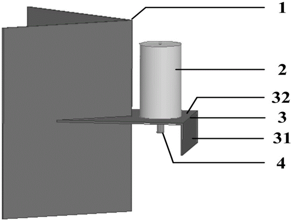
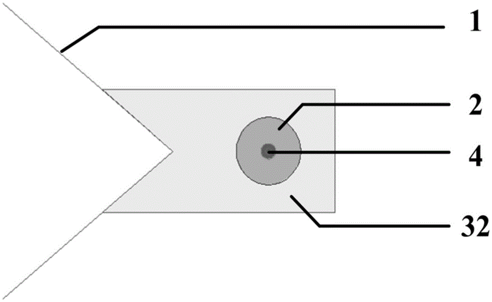
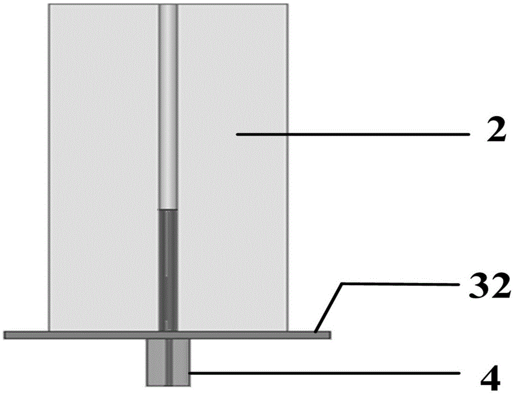
[0014] As shown in the figure, the dielectric resonant antenna provided by the present invention includes a metal reflector 1 , a dielectric cylinder 2 , a metal three-dimensional floor 3 and an antenna feeder 4 . Among them, the reflector 1 is made of conductive metal and has a dihedral structure. The dihedral opening angle is determined according to actual requirements, usually 30° to 45°. The relative dielectric constant of the dielectric cylinder 2 is also determined according to actual requirements. The dielectric constant is usually Between 9 and 10, the size varies with the operating frequency. The edge of the dihedral angle and the plane where the central axis of the medium cylinder 2 bisect the dihedral angle. The three-dimensional floor 3 is an L-shaped structure, usually an aluminum plate with a thickness of 2 to 6 millimeters; wherein the vertical surfac...


PUM


Abstract

The invention provides a dielectric resonant antenna with wide band and wide beam. In the technical scheme, the dielectric resonant antenna comprises an antenna feed line, a metal reflection plate, a dielectric cylinder and a metal vertical floor, wherein the reflection plate adopts a dihedral angle structure, a dihedral angle is divided equally by a plane where the edge of the dihedral angle and a central axis of the dielectric cylinder are located, the vertical floor is of an L-shaped structure and comprises a vertical surface and a parallel surface, the dielectric cylinder is placed on the parallel surface and is in seamless connection with the reflection plate, the vertical surface and the dielectric cylinder are arranged on the two sides of the parallel surface, an inner conductor of the antenna feed line is inserted into the dielectric cylinder, and an outer conductor of the antenna feed line is electrically connected with the vertical floor. The dielectric resonant antenna has the advantages of wide band and grain flatness in a relatively wide beam range.

Description

technical field [0001] The invention belongs to the technical field of wideband and wide beam antennas, and more specifically relates to a wideband and wide beam dielectric resonant antenna. Background technique [0002] With the development of radio information technology, wide-beam antennas play an increasingly important role in wireless communication systems. Especially in active array antennas, intelligent transmission systems, reconnaissance systems and security systems, wide beam antennas are widely used. [0003] Traditional wide-beam antennas often use a metal monopole plus a reflector, or a metal microstrip antenna plus a back cavity. The disadvantage is that the frequency band is narrow. In modern radio communication systems, especially in some reconnaissance equipment, wide-beam antennas with a certain frequency bandwidth are often required to meet specific reconnaissance requirements. Therefore, a dielectric resonant antenna with a lower dielectric constant can...

Claims


Application Information

Patent Timeline
Patent Type & Authority Applications(China)
IPC IPC(8): H01Q19/10
CPCH01Q19/106
Inventor 何艳杨虎陈国强康厚强林沂王禾
Owner NAT UNIV OF DEFENSE TECH
Learn More