Low-profile circularly polarized microstrip antenna for satellite communication

A satellite communication and microstrip antenna technology, applied in the field of satellite mobile communication, can solve the problems of not wide beam width, narrow working bandwidth, too large size, etc., and achieve the effect of good circular polarization performance

Inactive Publication Date: 2020-09-18
UNIV OF ELECTRONICS SCI & TECH OF CHINA
View PDF10 Cites 6 Cited by
  • Summary
  • Abstract
  • Description
  • Claims
  • Application Information

AI Technical Summary

Problems solved by technology

[0003] Literature "Son Xuat Ta, Chien Ngoc Dao, Kam Eucharist Kedze, Ikmo Park.:'Low-Profile Crossed-Dipole Antenna Loaded with Parasitic Patches', 2018International Workshop on An tenna Technology (iWAT), DOI: 10.1109 / IWAT.2018.8379175, 2018" discloses a low-profile cross-dipole antenna loaded with parasitic patches for GPS communication. By loading four parasitic patches between the cross-dipole antenna and the ground plane, the profile of the antenna is effectively Altitude reduced to 0.87λ 0 , and improve the working bandwidth of the antenna; the simulation results show that the final size of the antenna is 0.64λ 0 ×0.64λ 0 ×0.87λ 0 (λ 0 is the wavelength of the center frequency point in free space), the half-power beam width is 72°, the bandwidth of the VSWR<2 is 22.93%, the axial ratio (AR<3dB) bandwidth is 13.4%, and the axial ratio at the center frequency point is 1.5dB; but the disadvantage of this antenna is that the beam width is not wide and the profile is high
[0004] Document "Choi E.C, Lee J.W, Lee T.K,:'Modified S-band satellite antenna with isoflux p pattern and circularly polarized wide beamwidth',[J].IEEEAntennas and Wireless Propagati on Letters,2013,12:1319–1322" A satellite communication antenna for S-band is proposed. The main radiating element of the antenna is two pairs of butterfly-shaped crossed dipoles placed horizontally, and four parasitic elements are vertically loaded on the dipoles; by adjusting the horizontal crossed dipoles The height between the antenna and the reference ground and the area of ​​the vertically loaded parasitic element finally make the overall 3dB axial ratio beamwidth of the antenna greater than 140°, and the axial ratio at an elevation angle of 0° is less than 5dB; but the disadvantage of this antenna is that it is too large, The profile is higher, and the final simulation result shows that the antenna size is 0.41λ 0 ×0.41λ 0 ×0.55λ 0 (λ 0 is the wavelength of the center frequency point in free space)
[0005] The document "Yu-Xiang Sun, Kwok Wa Leung, Kai Lu.: 'Broadbeam Cross-Dipole Antenna for GPS Applications', IEEE Transactions on Antennas and Propagation., Vol:65, pp 5605–5610, 2017" discloses a method for using A crossed dipole antenna for GPS communication; the crossed dipole and the circular ground are printed on two orthogonally placed dielectric substrates respectively. The feed network of the antenna adopts a T-junction power distribution network, and the antenna is placed vertically as a whole In a cylindrical metal-backed cavity with corrugated edges; the bent printed dipole, circular ground and cylindrical metal-backed cavity with corrugated edges can improve the low-elevation angle gain of the antenna and broaden the beamwidth (axial ratio beamwidth , half-power beamwidth); it can be known from the simulation results that the axial ratio beamwidth (AR0 ×0.26λ 0 ×0.38λ 0 ,; but the disadvantage of this antenna is that the profile is high, the working bandwidth is narrow, and the installation is more complicated

Method used


Image

  • Low-profile circularly polarized microstrip antenna for satellite communication
  • Low-profile circularly polarized microstrip antenna for satellite communication
  • Low-profile circularly polarized microstrip antenna for satellite communication

Examples


Embodiment Construction

[0024] The present invention will be described in further detail below in conjunction with the accompanying drawings and embodiments.

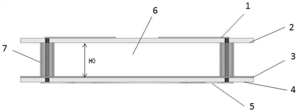
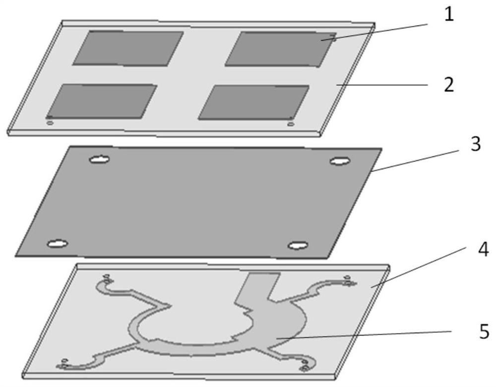
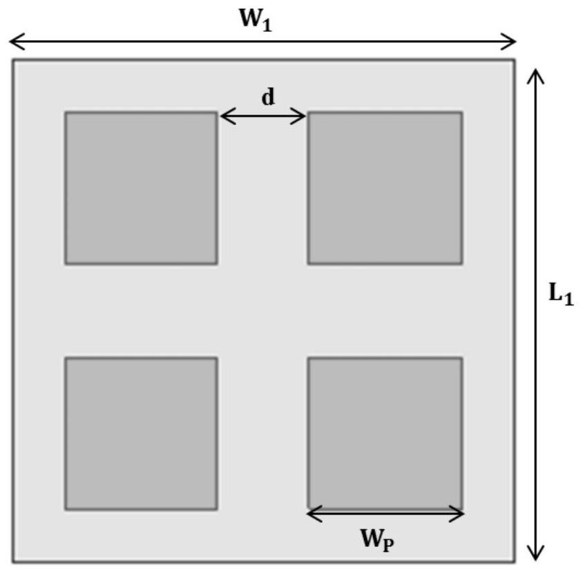
[0025] This embodiment provides a low-profile circularly polarized microstrip antenna for satellite communications, and its structure is as follows Figure 1 ~ Figure 4 As shown, it specifically includes: a radiation patch array 1, an upper dielectric substrate 2, a metal reflective layer 3, a lower dielectric substrate 4, a feed network 5, and a coaxial cable 7; wherein, the radiation patch array 1 is set on the upper dielectric On the upper surface of the substrate 2, the radiating patch array 1 is composed of four radiating patches arranged sequentially and rotated at equal intervals around the center of the upper dielectric substrate; the metal reflective layer 3 is arranged on the upper surface of the lower dielectric substrate 4, and the The feed network 5 is arranged on the lower surface of the lower dielectric substrate 4; the feed net...


PUM


Abstract

The invention belongs to the field of satellite mobile communication, and particularly provides a low-profile circularly polarized microstrip antenna for satellite communication, which is used for overcoming the problems of narrow beam width, higher profile, narrower working bandwidth, larger transverse size and the like of the existing satellite communication antenna. According to the invention,the microstrip four-element array design that the microstrip four-element arrays are arranged around the center of the upper dielectric substrate at equal intervals in sequence is adopted, so the antenna has good circular polarization performance; meanwhile, by adjusting the distance between the array elements, the current distribution of the diagonal array elements can be controlled, so the antenna realizes wide-beam radiation; moreover, an air layer is introduced between the radiator and the metal reflecting layer, and the bandwidth of the antenna can be broadened by adjusting the thicknessof the air layer. Most importantly, compared with an antenna with the same performance, the antenna has an extremely low profile, 0.068lambda0 can be achieved, and the antenna is more suitable for high-speed moving aerial or ground carriers with large wind resistance in satellite communication.

Description

technical field [0001] The invention belongs to the field of satellite mobile communication, and specifically provides a low-profile circularly polarized microstrip antenna for satellite communication. Background technique [0002] The types of circularly polarized antennas commonly used in satellite mobile communications mainly include helical antennas, microstrip antennas, and crossed dipole antennas. Compared with linearly polarized waves, circularly polarized waves have better flexibility in the orientation angle between transmission and reception, mobility, strong penetration energy of the ionosphere, and reduced multipath reflections or other types of interference; Therefore, circularly polarized antennas are widely used in various wireless systems. However, in many application systems, in addition to requiring the antenna to have a wide operating bandwidth, in order to ensure that the satellite communication system has sufficient communication links, the antenna is r...

Claims


Application Information

Patent Timeline
Patent Type & Authority Applications(China)
IPC IPC(8): H01Q1/36H01Q1/38H01Q1/50H01Q13/08
CPCH01Q1/36H01Q1/38H01Q1/50H01Q13/08
Inventor 唐璞王雪冯梅陈波姚远胡冰涛田径雷世文何子远包永芳杨伟陆平曾彬高银
Owner UNIV OF ELECTRONICS SCI & TECH OF CHINA
Why Eureka
Try Eureka