
Transverse vibration clamp adjustable in gravity center and angle

A lateral vibration, arbitrary angle technology, used in manufacturing tools, workpiece clamping devices, measuring devices, etc., can solve the problems of low test frequency, high cost, and overall bulky equipment, and achieve convenient torque control, versatility and stability. high effect

Inactive Publication Date: 2016-06-01
SUZHOU CHANGFENG AVIATION ELECTRONICS
View PDF10 Cites 3 Cited by
  • Summary
  • Abstract
  • Description
  • Claims
  • Application Information

AI Technical Summary

Problems solved by technology

Another traditional structure is to convert the vibrating table into a horizontal vibration plane through the guide rail mechanism, and then install the product on the vibrating table surface through the fixture. This kind of structure has high requirements for the horizontal guide rail vibration plane mechanism of the vibrating table, and the overall equipment is bulky High cost and low testing frequency

Method used


Image

  • Transverse vibration clamp adjustable in gravity center and angle
  • Transverse vibration clamp adjustable in gravity center and angle
  • Transverse vibration clamp adjustable in gravity center and angle

Examples


Embodiment Construction

[0013] The present invention will be further described below in conjunction with the accompanying drawings and embodiments, but the present invention is not limited thereto.

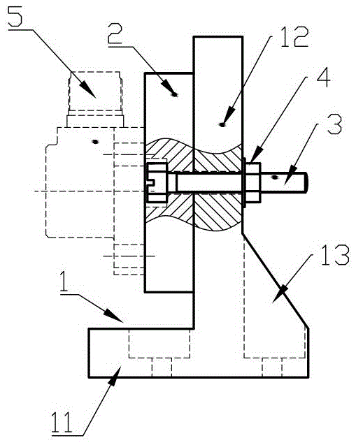
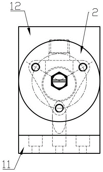
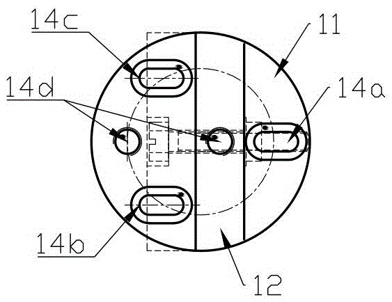
[0014] like Figure 1 to Figure 3 As shown, the transverse vibration fixture can be seen in general: it is composed of a base 1, an adapter plate 2, and matching bolts 3 and nuts 4. The base 1 is an inverted T-shaped structure in side view and the round bottom surface 1 of the base There are sensor mounting holes 14d and three parallel vibrating table mounting waist holes (14a, 14b, 14c) distributed in a triangular shape, the vertical wall surface 12 of the base 1 is perpendicular to the circular bottom surface 11, and the adapter plate 2 is passed through the bolt 3. The nut 4 is connected to the vertical wall surface 12 and can be rotated and adjusted by 360° (through the tightness of the elastic bolt and the nut), and the measured sensor 5 is fixedly connected to the surface of the connecting plate 2 ...


PUM


Abstract

The invention discloses a transverse vibration clamp adjustable in gravity center and angle. The transverse vibration clamp is formed by connecting a base, a connection plate, a bolt and a nut, wherein the bolt and the nut are matched; the base is of an inverted-T-shaped structure from the side view, a sensor installation hole and three kidney-shaped parallel vibration table installation holes distributed in a triangular mode are formed in the round bottom surface of the base, and the vertical wall surface of the base is perpendicular to the round bottom surface; the connection plate is connected to the vertical wall surface through the bolt and the nut, can rotate by 360 degrees and can be adjusted, and a tested sensor is fixedly installed on and connected to the surface of the connection plate. By applying the clamp, vibration tests can be realized in any direction of transverse 360 degrees; the gravity center can be adjusted, and the universality and the stability are high; the resonant frequency is high (the first resonant frequency is 7.8 kHz) and is higher than the upper suitable frequency limit (5 kHz) in GB / T 13823.8; the physical design is optimized, the transverse vibration ratio is smaller than 1.6%, the vibration amplification ratio (30 Hz) is smaller than 0.02%, and the vibration amplification ratio (160 Hz) is smaller than 0.3%; a hexagonal counter bore bolt is installed and fixed in the connection plate, and the torque is convenient to control.

Description

technical field [0001] The invention relates to a simple transverse vibration fixture for a vibration sensor that can be rotated freely at an angle of 360° and can be installed with an adjustable center of gravity, which is used for the transverse sensitivity test or calibration of the vibration sensor. Background technique [0002] Lateral sensitivity is a conventional index of the vibration sensor, which is used to assess the ability of the sensor to suppress 360° lateral interference, and this index is also an important index of the piezoelectric vibration sensor. Therefore, an angle-adjustable lateral vibration mechanism is needed for the lateral sensitivity test, and this structure is specially designed considering the angle adjustment, vibration stability adjustment, operability and practicability of the test. [0003] In the past, the traditional lateral vibration fixture was designed as a hexagonal or octagonal steel block structure with a fixed thickness, and the se...

Claims


Application Information

Patent Timeline
Patent Type & Authority Applications(China)
IPC IPC(8): B25B11/00G01H11/08
CPCB25B11/00G01H11/08
Inventor 章建文张磊全建龙倪泉彭溢润
Owner SUZHOU CHANGFENG AVIATION ELECTRONICS
Learn More