Pneumatic tire

A technology for pneumatic tires and tires, which is applied to tire parts, tire tread/tread pattern, transportation and packaging, etc., and can solve the problems of reduced wear resistance and rigidity

Active Publication Date: 2016-06-01
SUMITOMO RUBBER IND LTD
View PDF7 Cites 13 Cited by
  • Summary
  • Abstract
  • Description
  • Claims
  • Application Information

AI Technical Summary

Problems solved by technology

[0003] However, if the pneumatic tire is constructed to have such a tread pattern, for example, a problem arises that the rigidity of the pattern is reduced resulting in a decrease in abrasion resistance.

Method used


Image

  • Pneumatic tire
  • Pneumatic tire
  • Pneumatic tire

Examples


example

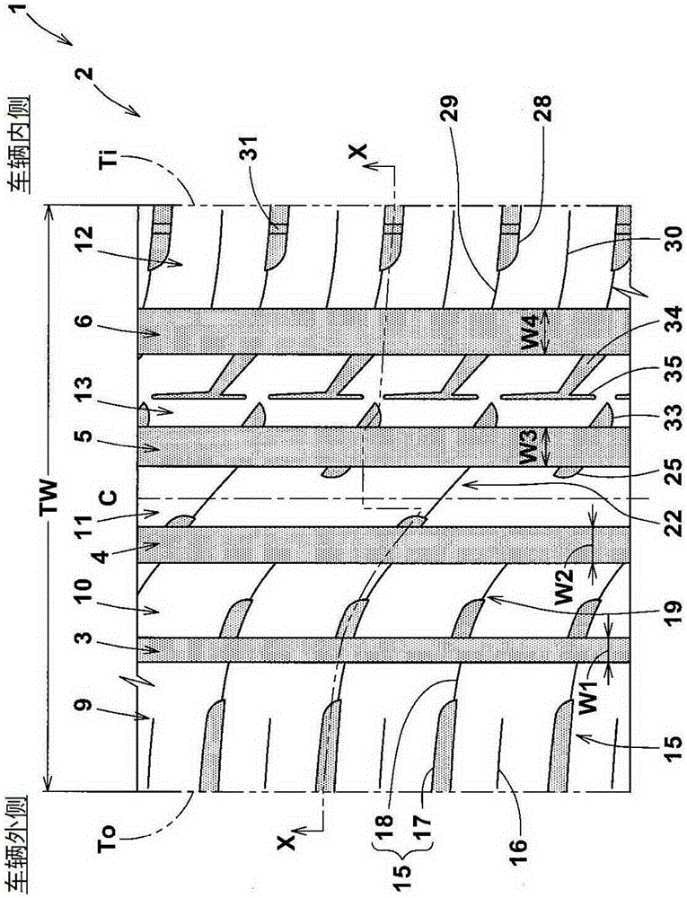
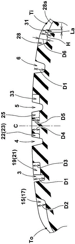
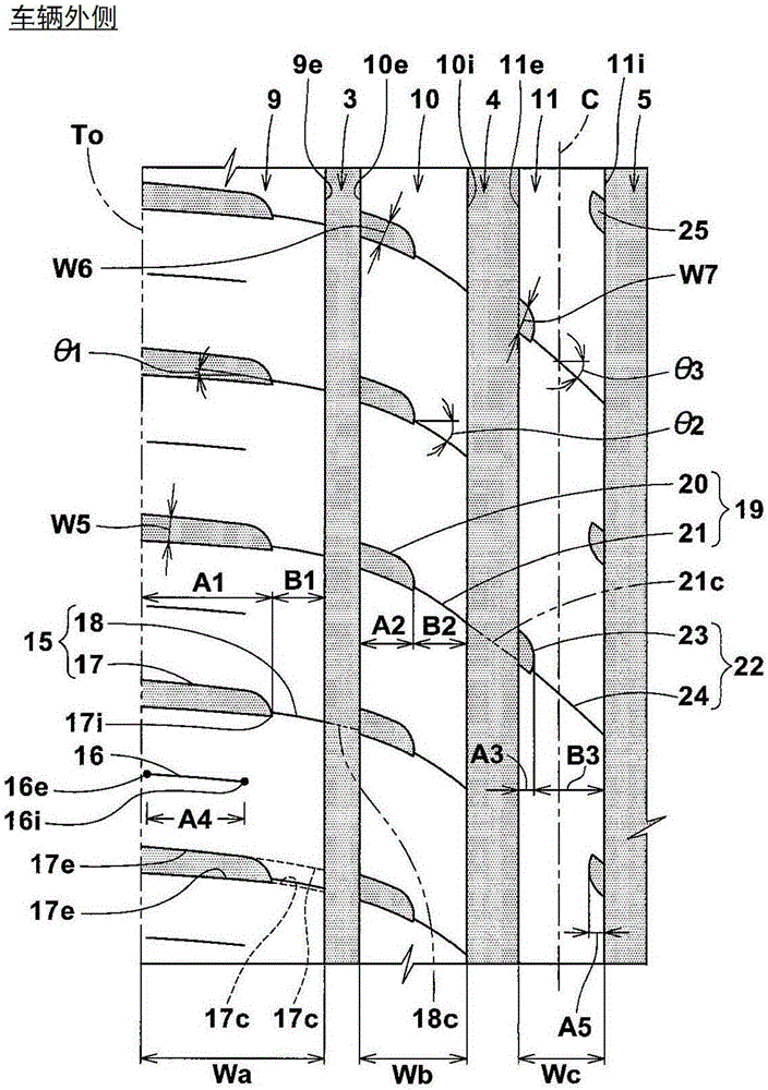
[0102] According to the specifications shown in Table 1, a pneumatic test tire of size 215 / 60R17 for passenger cars has figure 1 Basic pattern shown. Test them for abrasion resistance and wet performance. Common specifications for test tires and test methods are as follows.

[0103] Tread contact patch width (TW): 158mm

[0104] Groove depth of each main groove: 8.2mm

[0105] Maximum groove depth outside of the first transverse groove: 6.6mm

[0106] Groove depth of each outer part of the second and third transverse grooves: 5.8mm

[0107] Groove depth per sipe: 4.0 to 5.5mm

[0108] Groove depth of each sipe: 4.0mm

[0109]

[0110] In the following cases, test tires were mounted on all wheels of a front-wheel drive passenger car having a displacement of 2400 cc. The test driver drove 20,000km on a dry asphalt test road, 25% of which was gravel. Then, the degree of wear of the tire on the main grooves and on each outer portion of the transverse grooves was measured. ...


PUM


Abstract

To provide a pneumatic tire that exhibits well-balanced enhancement of wear resistance while maintaining high wet performance. [Solution(s)] On the tread 2, a pneumatic tire 1 is provided with a first tread edge (To), main grooves each extending continuously in a tire circumferential direction, land sections bordered by the main grooves, and lateral grooves crossing through the land sections. The land sections include a first land section 9 having the first tread edge (To) and provided with first lateral grooves 15, a second land section 10 adjacent to the inner side of the first land section 9 and provided with second lateral grooves 19, and a third land section 11 adjacent to the inner side of the second land section 10 and provided with third lateral grooves 22. Lateral grooves (15, 19, 22) each include an outer portion that extends from the first tread-edge (To) side land periphery and a sipe portion that is connected to the outer portion. Tire axial lengths (A1) 1/4 (A3) of outer portions and tire axial lengths (B1) 1/4 (B3) of sipe portions are specified at their respective values.

Description

technical field [0001] The present invention relates to a pneumatic tire that balances enhanced wear resistance while maintaining high wet performance. Background technique [0002] Pneumatic tires excellent in wet performance have been in high demand in recent years. In order to enhance the wet performance of pneumatic tires, it has been proposed to form main grooves and lateral grooves having larger volumes on the tread. [0003] However, if the pneumatic tire is constructed to have such a tread pattern, problems arise such that the rigidity of the pattern is reduced resulting in a decrease in wear resistance. [0004] prior art publications [0005] Patent Gazette [0006] Patent Publication 1: JP2012-116306A Contents of the invention [0007] The problem to be solved by the present invention [0008] The present invention takes the above problems into consideration, and its main object is to provide a pneumatic tire that balances enhanced wear resistance while mai...

Claims


Application Information

Patent Timeline
Patent Type & Authority Applications(China)
IPC IPC(8): B60C11/11B60C11/04
CPCB60C11/04B60C11/1369B60C11/0304B60C2011/1209B60C2011/0383B60C2011/0381B60C2011/0372B60C11/11B60C11/0327B60C11/1236B60C2011/0341B60C2011/0374
Inventor 木村真也
Owner SUMITOMO RUBBER IND LTD
Why Eureka
Try Eureka