Vehicle Pneumatic Tires

一种充气轮胎、车辆的技术,应用在充气轮胎的增强层、重型轮胎、重型车辆等方向,能够解决安排密度高、材料多、磨损不利影响等问题,达到高抗穿刺性和耐用性、良好摩擦作用、增强抗穿刺性和高耐用性的效果

Active Publication Date: 2016-01-20
CONTINENTAL REIFEN DEUTSCHLAND GMBH
View PDF5 Cites 0 Cited by
  • Summary
  • Abstract
  • Description
  • Claims
  • Application Information

AI Technical Summary

Problems solved by technology

Even with steel cords having a large cross-sectional thickness, the higher density of this arrangement (necessary to limit the risk of punctures) necessarily results in a belt ply that is heavy, material-intensive and has a detrimental effect on wear

Method used


Image

  • Vehicle Pneumatic Tires
  • Vehicle Pneumatic Tires
  • Vehicle Pneumatic Tires

Examples


Embodiment Construction

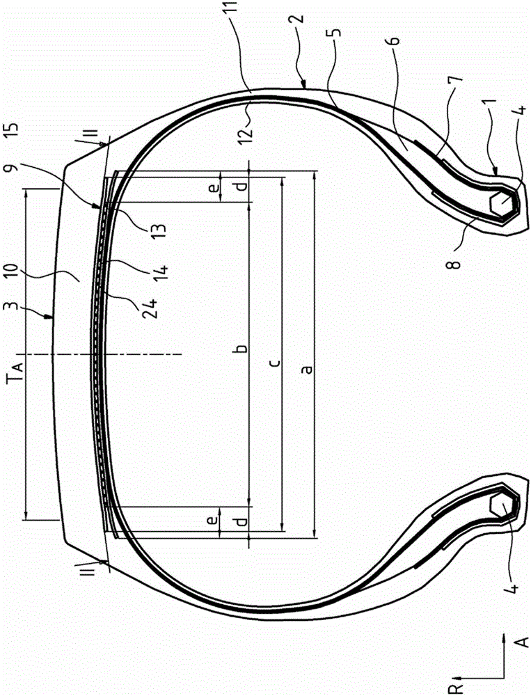
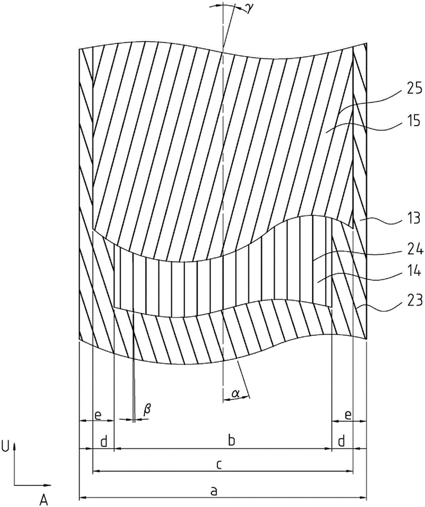
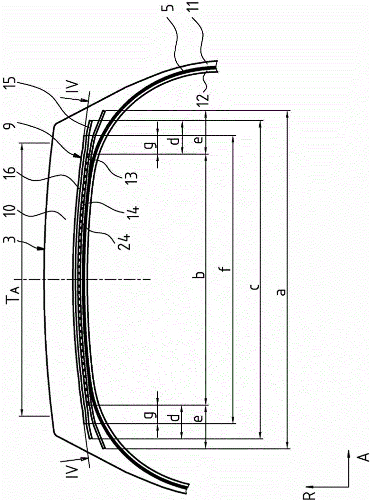
[0051] figure 1 and figure 2 Shown is a commercial vehicle pneumatic tire of radial configuration type with two sidewalls 2 extending in the radial direction R of the vehicle tire, and a Crown area 3. In this case the side walls 2 are designed at the end of their extension directed inwards in the radial direction R with a bead region 1 in which a bead core 4 of a known type is formed, The bead core is stretch-resistant in the circumferential direction U and extends over the circumference of the tire in the circumferential direction U. The bead cores 4 are designed by winding in a known manner steel wires extending in the circumferential direction U of the vehicle pneumatic tire and embedded in rubber. An apex (bead filler) 6 of triangular cross-section, made of a hard rubber material, is formed on the bead cores 4 in a conventional manner. The vehicle pneumatic tire is designed with a carcass 5 extending outwardly in the radial direction R of the vehicle pneumatic tire f...


PUM


Abstract

The invention relates to a vehicle pneumatic tire for commercial vehicles comprising a carcass (5), a belt (9) established radially outside the carcass (5), and a belt (9) radially on the belt ( 9) A shaped tread (10) built on the outside of the belt (9), wherein the belt (9) is formed by at least three belt plies (13, 14, 15), which Three belt plies are arranged on top of each other from radially inner to radially outer, wherein the radially inner belt ply (13) and the radially outer belt ply (15) is a working ply with steel reinforcing elements (23, 25) embedded in rubber and arranged at an angle of 10°-45° with respect to the circumferential direction, and which are arranged in The belt ply (14) between the two working plies (13, 15) is a belt ply (14) formed as a zero degree ply and having parallel reinforcements (24) which are The reinforcements are embedded in rubber and in their orientation comprise an angle β with respect to the circumferential direction U, where 0°≤β≤5°, wherein these reinforcements (23) of the two working plies (13, 15) , 25) each has a breaking force F of F>1800N, and has an elongation D under 10% breaking force of 0.22%≤D≤0.4%.

Description

technical field [0001] The present invention relates to a vehicle pneumatic tire, in particular for commercial vehicles, having a carcass, with a belt established radially outside the carcass, and with a A shaped tread built outwardly on the belt formed of at least three belt plies arranged one above the other from radially inner to radially outer position, the radially inner belt ply and the radially outer belt ply are working plies with parallel steel reinforcements embedded in rubber, the radial The reinforcements of the inner belt ply form an angle α with respect to the circumferential direction U in their orientation, 10° ≤ α ≤ 45°, and the reinforcements of the radially outer belt ply with respect to the circumferential The directions U form an angle γ, 10° ≤ γ ≤ 45°, and the reinforcements of one working ply have an inverse and the belt ply arranged between the two working plies is a belt ply which is designed as a zero-degree ply and has parallel reinforcing These r...

Claims


Application Information

Patent Timeline
Patent Type & Authority Patents(China)
IPC IPC(8): B60C9/20B60C9/22
CPCB60C2200/06B60C2009/209B60C9/2006B60C2009/208B60C9/22B60C9/20B60C2009/2012B60C2009/2074B60C2009/2214
Inventor 特蕾西娅·贝克尔迈克·舒尔特克里斯托夫·拜代尔瑙
Owner CONTINENTAL REIFEN DEUTSCHLAND GMBH
Why Eureka
Try Eureka