vehicle pneumatic tires

A technology for pneumatic tires and vehicles, which is applied to vehicle parts, tire parts, tire treads/tread patterns, etc., can solve the problems of limited wet characteristics and ice grip characteristics, and achieve good handling characteristics, simple implementation, The effect of good ice grip

Active Publication Date: 2017-03-08
CONTINENTAL REIFEN DEUTSCHLAND GMBH
View PDF4 Cites 0 Cited by
  • Summary
  • Abstract
  • Description
  • Claims
  • Application Information

AI Technical Summary

Problems solved by technology

However, such a sinusoidal or corrugated design only provides a punktuellen effective contact in the region of its crests or troughs for gripping on wet roads or ice, thus limiting wet characteristics and ice contact. Grip characteristics

Method used


Image

  • vehicle pneumatic tires
  • vehicle pneumatic tires
  • vehicle pneumatic tires

Examples


Embodiment Construction

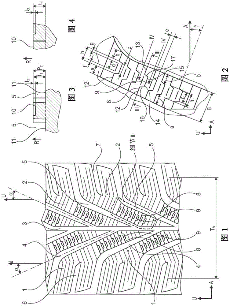
[0024] 1 to 4 show a tread pattern of a vehicle pneumatic tire for passenger cars (PKW), which has a tread pattern oriented in the circumferential direction U of the vehicle pneumatic tire and a central circumferential groove 3 extending circumferentially, which divides the tread pattern into two tread halves arranged adjacent to each other in the axial direction A of the vehicle pneumatic tire middle. The tread halves shown on the right in FIG. 1 are distributed over the circumference of the vehicle pneumatic tire and form rib-shaped, radially raised tread elements 2 of known type arranged one behind the other in the circumferential direction U , these tread elements each extend in the axial direction A starting from the circumferential groove 3 to a position in the right shoulder outside the bottom support surface width TA and stop there. The bottom bearing width TA is the width of the part of the tread in contact with the ground which complies with the E.T.R.T.O. interna...


PUM


Abstract

The invention relates to a tread profile of a vehicle pneumatic tire having a first fine notch (8) in the primary extension direction in the radial outer surface (10) made of at least one first (12) and one second (13) extension section, designed at a distance h from each other in succession, wherein the first fine notch (8) is designed extending on a common, substantially linear extension line, and from a third extension section (14), formed between said two extension sections (12, 13), which connects the two extension sections (12, 13) and wherein the first fine notch (8) is designed having no further interface along the entire extension thereof, and between the first (12) and the second (13) extension section of the first fine notch (8), an additional second find notch (9) is designed, extending in a linear manner on the common extension line and having a distance to the first fine notch (8).

Description

technical field [0001] The invention relates to a tread pattern of a pneumatic tire for vehicles having radially raised tread elements delimited in the axial direction A by at least two sipe or grooves and having a first thin cut, These first fine cuts delimit respectively in the radially outer surface of such a tread unit a sipe or groove of the tread unit towards one axial side on the one hand and a tread towards the other axial side on the other hand between the grooves or grooves of the unit, wherein the first thin cut in the direction of its main extension in the radially outer surface consists of a first extension section and a second extension section formed one behind the other at a distance h section and is formed by a third extension section formed between these two extension sections, in the first extension section and the second extension section, the first fine cuts are respectively in a substantially straight common Extended on the extension line, the third exte...

Claims


Application Information

Patent Timeline
Patent Type & Authority Patents(China)
IPC IPC(8): B60C11/12
CPCB60C11/0302B60C11/1236B60C2011/0374B60C2011/1213B60C2011/1254B60C2011/129
Inventor 斯特凡·里特韦格马里耶勒·诺加乌尔里希·费梅尔
Owner CONTINENTAL REIFEN DEUTSCHLAND GMBH
Why Eureka
Try Eureka