Method for manufacturing heat exchanger and heat exchanger obtained by same

A manufacturing method and heat exchanger technology, applied in the direction of indirect heat exchangers, heat exchanger types, manufacturing tools, etc., can solve the problems of reduced strength, difficulty in joining, and insufficient supply of thin tubes and straight tubes. Achieve the effect of uniform thickness and low cost

Inactive Publication Date: 2014-08-27
UACJ COPPER TUBE CORP
View PDF10 Cites 4 Cited by
  • Summary
  • Abstract
  • Description
  • Claims
  • Application Information

AI Technical Summary

Problems solved by technology

However, in such a manufacturing method using the steps of winding thin tubes-bending-furnace brazing, the brazing temperature is as high as 800°C, so the temperatures of the core tube and the thin tube as the base material become high. , as a result, the grain size becomes large and the material softens, so there is a problem that the strength decreases and becomes a cause of leakage
In addition, brazing is performed after the bending process. Therefore, there is also a problem that the core tube is flat at the bent portion due to the lack of joint between the core tube and the thin tube, and the pressure loss on the water passage side becomes large. Such a problem: the thin tube leaves the core tube, and there is a gap between the thin tube and the core tube, which makes it difficult to join, resulting in a large thermal resistance
However, there must be a predetermined gap between the contact portion between the thin tube and the straight tube or the contact portion between the thin tube and the core tube. In this form, the linear brazing material wound together with the thin tube , The solder wire is wound on the straight tube and the core tube and positioned on one side of the thin tube, so when the above-mentioned linear brazing material and solder wire are melted by heating, the brazing material, The molten material of the solder is biased to one side of the thin tube, and sometimes it cannot be sufficiently supplied to the contact portion between the thin tube and the straight tube or the contact portion between the thin tube and the core tube, and the melt is self-sustained before bonding. The straight tube or the core tube is melted and dripped, and therefore, there are problems such as that it is difficult to effectively perform bonding between the thin tube and the straight tube or between the thin tube and the core tube. There is a gap between the tube and the straight tube or between the above thin tube and the core tube, resulting in a non-joint part

Method used


Image

  • Method for manufacturing heat exchanger and heat exchanger obtained by same
  • Method for manufacturing heat exchanger and heat exchanger obtained by same
  • Method for manufacturing heat exchanger and heat exchanger obtained by same

Examples


Embodiment Construction

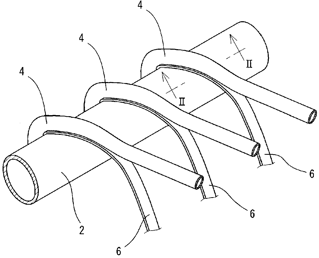
[0025] When manufacturing a heat exchanger for hot water supply that uses carbon dioxide as a refrigerant, one of the heat exchangers that is the object of the present invention, it is known to adopt a manufacturing method including a winding step for Winding one or more refrigerant tubes around the outer peripheral surface of a straight tube-shaped water pipe; joining step for joining the refrigerant tube to the outer peripheral surface of the water pipe; and bending step for bending the obtained joined body It is processed into a spiral shape or a racetrack shape, but here, according to the present invention, a strip-shaped solder sheet material is used as a bonding material, and the winding process of the refrigerant tube is performed.

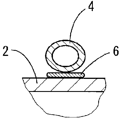
[0026] Specifically, as figure 1 As shown, one or more, in this case three refrigerant tubes 4, are spirally wound on the outer peripheral surface of a straight tube-shaped large-diameter water tube 2 with a water passage in the tube. The ...


PUM

PropertyMeasurementUnit
widthaaaaaaaaaa
thicknessaaaaaaaaaa

Abstract

Provided is a method of joining a large diameter water pipe to a small diameter refrigerant pipe to manufacture a heat exchanger, such that dropping of molten solder is advantageously prevented and effective joining of the water pipe to the refrigerant pipes is achieved while reduction in the strength of base materials is effectively suppressed. In the manufacture of a heat exchanger formed by joining a small diameter refrigerant pipe to the outer peripheral surface of a large diameter water pipe, strip-like solder plate material is used for the joining material, and after the solder plate material is mounted on the outer peripheral surface of a water pipe so as to be sandwiched with the refrigerant pipe, the solder plate material is melted by heating to a temperature that does not exceed 350 DEG C, and the water pipe and refrigerant pipe are joined.

Description

technical field [0001] The present invention relates to a manufacturing method of a heat exchanger and the heat exchanger obtained by the manufacturing method, in particular to a heat exchanger for hot water supply that can be advantageously manufactured by winding and joining refrigerant pipes around water pipes. heater technology. Background technique [0002] Conventionally, there is known a heat exchanger composed of a large-diameter water pipe with a water passage in the pipe and a refrigerant pipe with a diameter smaller than that of the water pipe. As one of the heat exchangers, the heat exchanger for hot water supply is used in the following form, that is, the water pipe with a large diameter is bent and processed into a racetrack shape (Japanese: トラック shape) or a swirl shape ( Japanese: scroll き shape), and to spirally wind around the water pipe, joining one or more refrigerant pipes with smaller diameters. [0003] In addition, in order to manufacture such a heat...

Claims


Application Information

Patent Timeline
Patent Type & Authority Applications(China)
IPC IPC(8): B23K3/06B23K1/00F28D7/02B23K101/14B23K103/12
CPCB23K2203/12B23K3/021F28D7/024B23K2201/14B23K2201/08F28D7/0008F28F2275/04C21D9/50B23K35/0222B23K1/19B23K1/0012B23K3/043B23K3/0623B23K2101/14B23K2103/12C21D2251/04C22C9/00C22C13/00
Inventor 西本嘉弘鸟山治饭岛泉
Owner UACJ COPPER TUBE CORP
Why Eureka
Try Eureka