
Lifting unit for lifting and lowering a container in a container treatment assembly

A lifting unit, processing equipment technology, applied in liquid handling, transportation and packaging, packaging, etc., can solve problems such as high energy loss

Active Publication Date: 2016-06-01
KRONES AG
View PDF6 Cites 2 Cited by
  • Summary
  • Abstract
  • Description
  • Claims
  • Application Information

AI Technical Summary

Problems solved by technology

[0004] A disadvantage of lifting devices in the form of pneumatic lifting cylinders is that, in order to raise or lower the container holding device and to provide or maintain a pressing force, an air pressure applied to the lifting cylinder must always be provided which is sufficiently great that even when the Also provides the necessary extrusion force during processing
However, providing higher air pressure throughout container handling results in higher energy losses
In addition, the entire hydraulic system must be provided to generate the desired high pressure and must provide high pressure over the entire treatment angle

Method used


Image

  • Lifting unit for lifting and lowering a container in a container treatment assembly
  • Lifting unit for lifting and lowering a container in a container treatment assembly
  • Lifting unit for lifting and lowering a container in a container treatment assembly

Examples


Embodiment Construction

[0051] A preferred exemplary embodiment is subsequently described with reference to the drawings. Identical, similar or identically acting components are identified here with the same reference symbols. In order to avoid redundant description, repeated descriptions of these components are partially omitted in the following description.

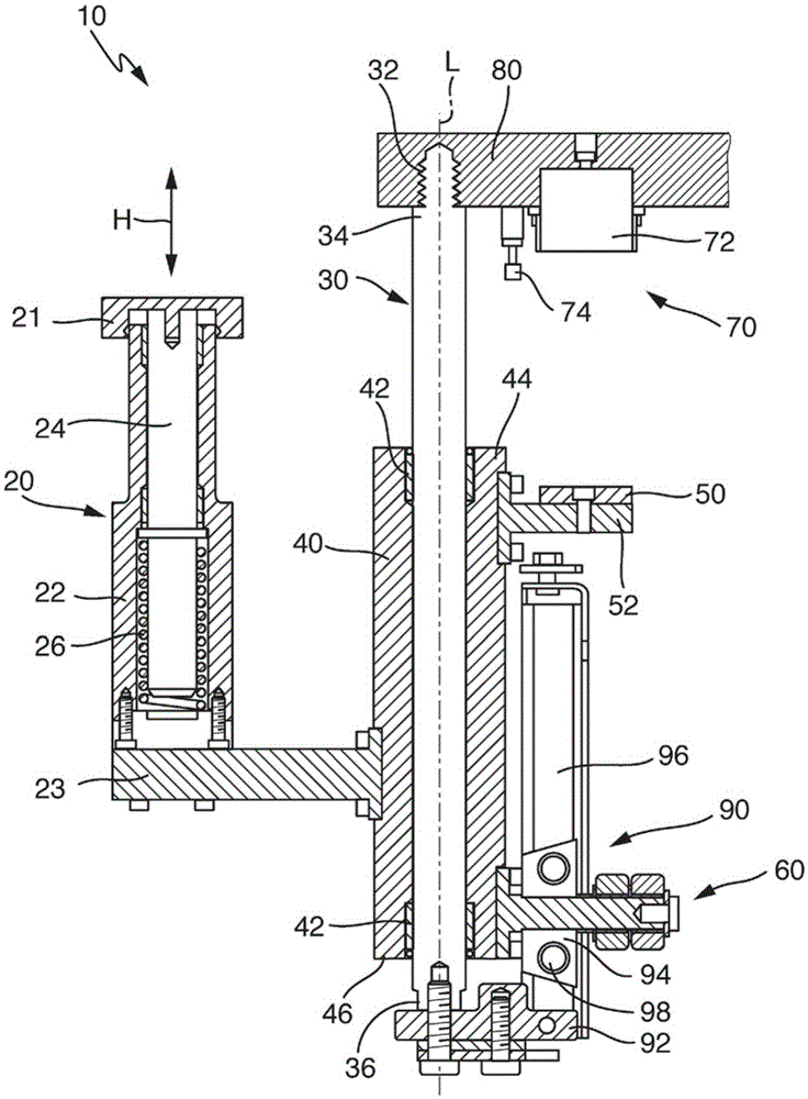
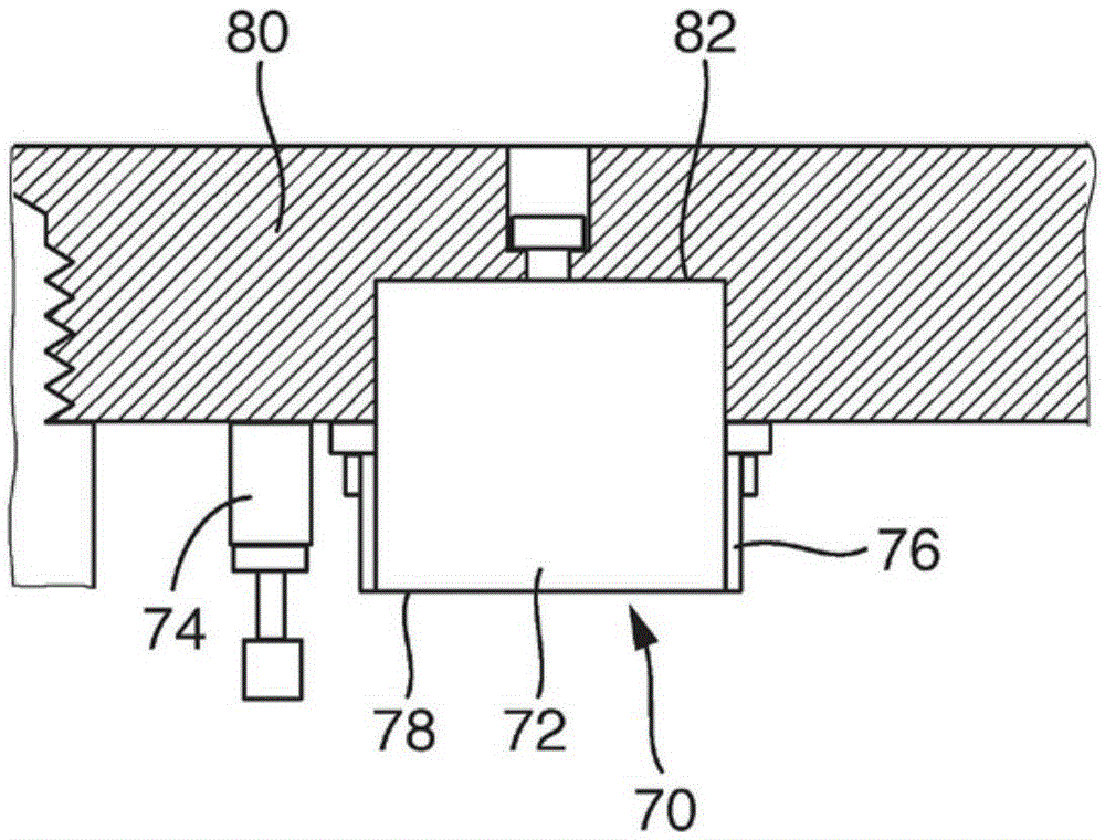
[0052] figure 1 A lifting unit 10 is shown, which can lift and lower containers in a container processing plant. For this purpose, the lifting unit 10 has a container holder 20 on which the containers can be arranged. The container holder 20 is guided via a bearing 40 onto the first guide 30 and can be raised and lowered via a lifting device 60 . For the corresponding container handling, a locking device 70 is provided on the support plate 80 of the swivel part, which locks the armature 50 arranged on the bearing 40 so that the container holding device 20 is held in a predetermined position.

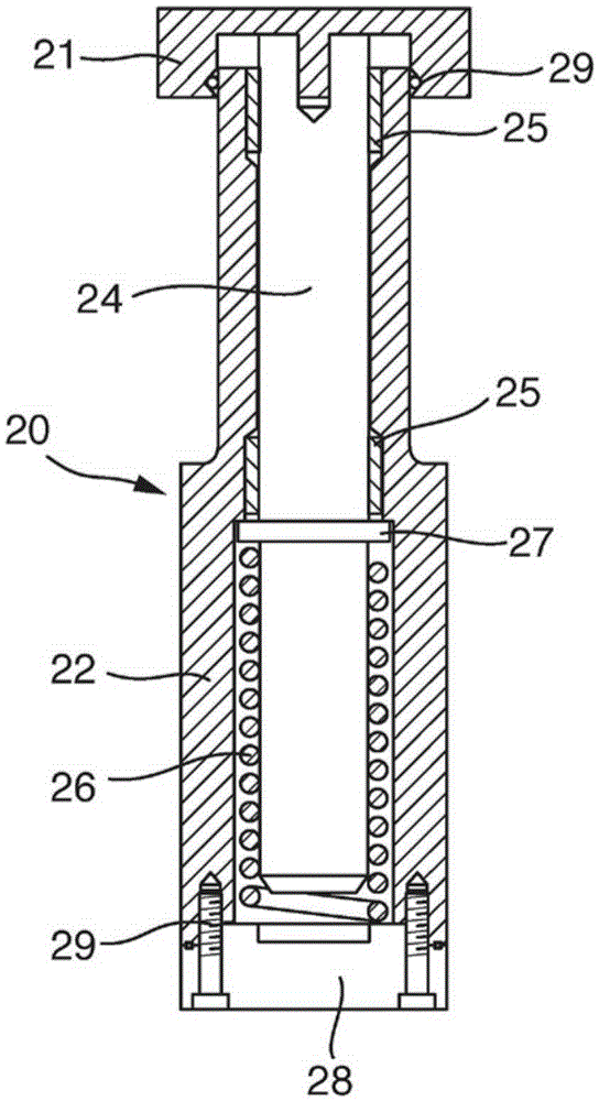
[0053] figure 1 and 3 The container holding ...


PUM


Abstract

The invention relates to a lifting unit (10) used for lifting and lowering a container in a container treatment assembly. The lifting unit includes a container fixing device (20) used for holding the container, a lifting device (60) used for lifting and lowering the container fixing device (20) and a locking device (70) used for locking the container fixing device (20) in a preset position, wherein the locking device (70) is magnetic.

Description

technical field [0001] The invention relates to a lifting unit for raising or lowering containers in a container handling plant, comprising: a container holding device for holding the container, a lifting device for raising and lowering the container holding device and a container holding device for Locking device locked in a preset position. Background technique [0002] For example, during container processing in a rotary filler, the container to be processed traverses a processing angle along which the container to be processed is pressed against the processing device. The provision of a pressing force of the container relative to the handling device is particularly necessary, since otherwise the forces acting on the container during handling may lead to separation of the contact between the container and the handling device. Such forces occur, for example, when the container comes into contact with the filling valve and is pre-compressed by gas. When filling a containe...

Claims


Application Information

Patent Timeline
IPC IPC(8): B67C3/24
CPCB67C3/24B67C3/246
Inventor 罗兰德·劳梅尔斯特凡·珀尔斯尔丹尼尔·伊巴涅斯·戈麦斯
Owner KRONES AG
Learn More